
Longer Drawing Machine - LONGER
Longer Drawing Machine

A Pen Plotter is a Drawing Machine that is positioned between a 3D printer and a Laser Engraver, since it has characteristics of both of them. In fact, it uses a three-axis Cartesian XYZ system (like a 3D printer) to make 2D images (like a Laser Engraver) using a pen. In simple words, this machine allows you to draw as you do by hand, but with the precision and handwriting of a computer.

This guide allows you to make a Pen Plotter using any Longer FDM 3D printer as a base. The change does not alter printing capabilities but is an added feature. Note that this guide is not compatible with printers equipped with BL-TOUCH leveling sensors.

Preparation of the machine

  1. Download and print this pen holder:

https://drive.google.com/file/d/1gwQJZo7U1t-0NzUbUzdNdexHfIp1fW4g/view?usp=sharing

  1. Screwdown the two screws placed to the left of the head module and the pen support (the dual blower module already provides two holes where to install the pen support)

  1. Proceed to normal leveling of the printer, using the sheet of paper to level the nozzle and the glass of the hotbed
  2. After leveling the print bed, remove the glass and replace it with a sheet of paper; Since the sheet of paper is thinner than the glass, the nozzle will be very far from the sheet of paper, but this is normal
  3. Insert a pen inside the pen holder; the pen must be in contact with the sheet of paper, the tip of the pen must touch the paper to be able to write, then secure the pen using a screw through the support

  1. Using a test sheet, test whether moving the x-axis can write to all points on the sheet
  2. To prevent the filament sensor from reporting an error, insert a piece of filament through the filament sensor; also, disconnect the extruder motor E cable

Preparation of the Drawing File

  1. After choosing a 2D image without background (like this one above in the figure), open the "3D Builder" software preinstalled in Windows 10 (if it was not present, download it from the Windows Store). Then select "Open – Load image" to import the selected image.

  1. Once the image has been imported into 3D Builder, you can change some settings such as Levels, Smooth, and so on; using these settings, edit the file according to your preferences. Once the editing is complete, select Import Image to get the image converted to 3D file.

  1. At this point, assign to the 3D model aheight "Z" of 0.1 mm; in fact, a drawing can be considered as a 3D model composed of a single layer, therefore assigning a thickness of 0.1 mm then the printer finishes the work after the first layer
  2. When the 3D model is ready, proceed to export, selecting "Save as - . STL".

Drawing printing procedure

  1. Import the previously created "3D" drawing into Cura
  2. At this point, the design can be made either full or with only the outline a.To make a full drawing, make sure "Top/Bottom Thickness" is set to "1"

b.To create a blank drawing, with edges only, make sure "Top/Bottom Thickness" is set to "0"

  1. Export the Gcode, proceed to print, and here is the final result

  1. Download here some sample model, enjoy your new Longer Drawing Machine!

https://drive.google.com/file/d/1K4Adp4pt1v9ypqZ2ytmCrK679k0XrAsy/view?usp=sharing

https://eu.longer.net/products/lk5-pro-fdm-3d-printer

By Software | December 12, 2022
Longer Fanducts for FDM 3D printers - LONGER
Longer Fanducts for FDM 3D printers

All FDM 3D printers are equipped with some fans, each of which performs a different function. For example, one fan cools the mainboard, another fan cools the hotend, and so on.

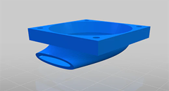
A fan with relevant functionality is the cooling fan of the printed filament, which is a fan that cools the print, so as to allow the filament to solidify quickly, avoiding deformation in the print due to heat. This fan can not do anything on its own, and in fact it is always associated with a "fanduct", or a duct through which the air emitted by the fan passes, which is concentrated and directed correctly on the print.

Fanducts come in various shapes and sizes, while all maintaining the same function; depending on its design, the fanduct can concentrate more or less air, in one or more directions. Here's a list of official Longer 3D fanducts, each with different features for different purposes:

  • Classic Fanduct

This fanduct is the default model of Longer 3D printers, it allows you to concentrate a large amount of air and cool a large portion of the print at the same time thanks to its round output. It is perfect for prints with large surfaces, prints that are printed at high speed and for prints made with very large nozzles.

Download link: https://www.thingiverse.com/thing:5585284

  • Precision fanduct

This Longer 3D fanduct is the one that concentrates the air the most, and then directs it at high pressure and speed at a single point. In fact, due to the great difference in section between inlet and outlet, the air accumulates a great speed at the outlet, thus being able to cool the affected printing part in a few moments. Its main use is for prints with many detailed parts and very thin parts that extend upwards; For example, trying to print a tip, usually the heat causes a deformation due to the collapse of the structure, instead with this fanduct it is possible to dissipate heat quickly, largely solving the problem.

Download link: https://www.thingiverse.com/thing:4860509

  • Longer Dual Blower Kit

The new Longer Dual Blower has been specially designed to allow a faster and more uniform emission of cooling air, thanks to two bilateral turbo fans and a double ventilation duct; in this way the prints are much more detailed and the bridging printing greatly improved.

  • The installation is very simple, and can be done by consulting this video guide:

https://youtu.be/zEA-eM5sfho

  • The purchase is available on the Official Longer Store:

https://eu.longer.net/collections/accessories/products/longer-new-dual-blower-fan-kit

The fanducts of the Dual Blower are totally 3D printable, stl files are available if necessary.
Download link: https://www.thingiverse.com/thing:5585281

https://eu.longer.net/products/lk5-pro-fdm-3d-printer

By Software | December 12, 2022
Diode Laser Engraver (450 nm) vs CO2 Laser Engraver (1024 nm) - LONGER
Diode Laser Engraver (450 nm) vs CO2 Laser Engraver (1024 nm)

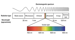
In physics, the propagation in space of electromagnetic field energy is called electromagnetic radiation. Depending on the wavelength, the radiation takes on a different nomenclature; in particular, electromagnetic radiation with a wavelength between about 400 nm and 700 nm is called visible radiation and is perceptible by the human eye and transformed by the brain into visual sensations; this radiation is what is commonly called light.

electromagnetic spectrum

Frequency and wavelength are inversely proportional quantities, i.e., when the wavelength decreases, then the frequency increases. Radio waves, also used for FM and TV broadcasts, are in the MHz range; instead, microwaves are on the order of GHz. Instead, visible light is already in the order of THz and then increases more and more in the rays due to nuclear decay, which, however, have a minuscule wavelength. Note that with the same power, electromagnetic radiation is able to pass through matter more easily when it has a longer wavelength (i.e., lower frequency); a trivial example is the ability of radio waves to pass through the walls of a house, while sunlight is shielded.

By analyzing the laser beams, they therefore take on a different color according to the wavelength; a blue beam (like the Longer Ray5 laser) has a wavelength of 450 nm, while green or red laser beams have different lengths. However, a laser beam does not necessarily belong to the visible spectrum, as it can also be generated as a different radiation. For example, there are some lasers belonging to the infrared, which are invisible but retain their abilities.

An example of an infrared laser is the CO₂ laser, which is a laser characterized by a wavelength between 940 nm and 1060 nm, which is generated within an active laser medium contained in an air- or water-cooled gas discharge tube. The gas contained within the laser tube consists mainly of carbon dioxide (CO2) and other gases, where an initial gas is excited by electric current but is not able to release a photon because of its chemical structure and then transfers its energy to a CO2 molecule that triggers the first photon. The operation is similar to a neon/fluorescent bulb, although in this case the photons generate a laser beam instead of optically isotropic light.

Given the high power obtainable (as the ratio between input and output power is very high), CO₂ lasers are widely used for metal engraving, for cutting materials, and for industrial welding. They are also very useful in surgery because the main constituent, water, of the cells absorbs very well the emitted infrared frequency. In addition, CO₂ lasers are also used for telemetry, as infrared can pass through the Earth's atmosphere easily, being almost completely transparent to infrared.

https://eu.longer.net/collections/laser-engraver

By Software | November 8, 2022
Step-Down Converters & Voltage Regulators

Many owners of Longer 3D printers love to customize the machine with additional accessories, LED lighting, and so on. However, each accessory works at a specific electrical voltage and requires a certain current, so attention should be paid to the technical specifications of each of them; in fact, Longer printers generally work at 24V, so it is not enough to simply connect the accessories to the mainboard of the printer or to its power supply, since this could compromise the operation of both the printer and the accessories.

NOTE: This guide is only for an electronically savvy audience! Misinterpretations could cause accidents and damage to equipment. If you don't feel confident, don't try the changes but talk to an expert.

In order to lower the voltage from 24V to a lower one it is necessary to cause a "Potential Difference Drop". The most basic method in physics to achieve this is the use of a resistor, however it dissipates all the current absorbed in the form of heat, so it is an inefficient and unstable method, since it depends on many factors. Nowadays there are various electronic components that can perform this function in an excellent way, and given their really low cost it is really worth considering to be able to operate safely. Here is a description of the best components on the market.

XH-M401

This voltage converter allows you to adjust the potential difference downwards efficiently and supports a high current passage thanks to the presence of two power mosfets. Connected to one of the outputs of the printer's power supply, it allows you to adjust the voltage between 24V ~1V, so it is ideal for connecting 12V & 5V LED lamps that require high current absorption, to connect 12V & 5V fans, to connect camcorders that require a specific voltage, or any other type of accessory.

L7812

This linear voltage regulator allows you to adjust a voltage of 35V max in a voltage of 12V output, however the output current is 1A max and also dissipates in the form of heat; for this reason, the voltage regulator has a hole, as it must be fixed with a screw on top of an aluminum bracket in order to reduce its temperature. Using this regulator, it is possible to reduce the voltage from 24V to 12V, however its use is limited to accessories that require a very low current (for example, a 12V fan), and in any case the regulator must be dissipated by fixing it to the printer frame taking care not to cause short circuits.

L7805

This linear voltage regulator, similar to the L7812 regulator, allows you to reduce the voltage by having a 5V output. It is often used to reduce voltages of 12V towards 5V, however it can also be used to reduce the 24V of the machine in 5V even if the dissipation in the form of heat will be really excessive. It is strongly discouraged to use this voltage regulator allows, preferring in its place the XH-M401 regulator.

SZBK07 300W/20A (for special applications)

This voltage converter can be too elaborate, as it allows both to adjust the output voltage and to limit the max current absorbed by the connected component in output. This turns out to be the best compromise to power driver-free LEDs, battery charging and other applications that require special attention. It is exposed here only for information, as accessories for 3D printers do not require such precautions.

https://eu.longer.net/collections/3d-printers-1

By Software | September 30, 2022
3D RESIN PRINTER REVIEW | DON'T UNDERESTIMATE THE MIGHTY ORANGE 30 - LONGER
3D RESIN PRINTER REVIEW | DON'T UNDERESTIMATE THE MIGHTY ORANGE 30
Longer 3D as a company has FDM and Resin printers but also sells laser engraver machines.

Here are some of the specs about the Orange 30.

  • High precision & Uniform Matrix UV lighting
  • 2.8 inch Touch screen & faster printing speed
  • Fast Cooling & high-Temperature warning system
  • Affordable price: $149.99 or £130

This Printer started out on Kickstarter in 2019 and was successfully funded there. The vat has been updated by Longer since it was released and is a plastic one compared to the metal one originally.

So its a 2K LCD screen at 2560 X 1440 resolutions and 47.25µm pixel size, the build plate is 120mm(L)*68mm(W)*170mm(H); With a solid linear guide and special slider design, it will ensure the accuracy and stable of Z-axis.

So I set about unboxing the printer live over at my Twitch channel, it comes well packed in a box with lots of protection for it, one of the first things I noticed about this resin printer is that you need to assemble the UV cover as it is flat picked and has a paper covering both sides of it to protect from scratches.

Assembling the UV cover took the longest to do as the paper that needed taking off was stuck well to the plastic. Once this was done it was a little tricky getting the elastic bands on it to hold it together, but if you don’t wish to use the elastic bands that come with the printer you can find STL files for a system to hold it together a bit better, as I always feel it's going to fall apart in my hands when moving the lid about.

Putting the vat on is straightforward as always and it was a quick process to level the build plate.

Once I've done everything I put the USB drive into the printer and see that there were 4 test files, so I set about printing them all, they all came out fantastic as I would expect from a resin printer, the touch screen is responsive and nicely laid out and easy to navigate it.


I set about slicing some of my own files I wanted to print on it and if you want you can use Longer 3D own slicer for it, but I use Lychee Slicer as my go-to slicer these days. It was easy to add the printer to the slicer, you just need to make sure you save the file to the USB drive as a .lgs30 file for the printer to read it.

Ok so it’s not the biggest of build plates for a resin printer, but don’t let that fool you. I found this printer was able to print everything I was slicing for it, I had one failure out of about 30 prints and that was down to human error as I didn’t add supports correctly. The print quality is good especially for a 2k resin printer, it wasn’t overly loud when it was printing and I didn’t notice any bad smells of resin coming from it, which I do use an air purifier next to all my resin printers just for some added protection.

So who is this resin printer aimed at? That’s a good question, I think that this might just be one of the best entry-level resin printers that you can buy at the moment, resin printing can be expensive if you are starting out in it, printer, wash and cure station, IPA for the wash and gloves, etc, it starts adding up. So if you purchased this as your first resin printer and you found out that resin printing wasn’t for you, it's not a big amount of money spent on the Orange 30 and I’m sure you will find a buyer for it if you put it up for sale.

If you are an experienced resin user already you might possibly have bigger resin printers that you use, like myself, recently I was printing a Wicked3D STL which was a decent size, and I used 3 resin printers to print all the parts for it and the Orange 30 fitted perfectly for printing the small parts for it, in-between my bigger resin printers, some people use resin printers for small tabletop figures and I’m sure you would be able to get a good amount of them on the build plate of the Orange 30.

So in conclusion I think that this resin printer is ideal for all users, especially for the price. I have been printing litho on this printer too and the photo quality is good. if you were to invest in this I think most people would be pleased with the results of the prints.


https://eu.longer.net/products/orange-4k-resin-3d-printer

By Software | September 21, 2022
Air Assist Kit installation for Longer Ray5 10W - LONGER
Air Assist Kit installation for Longer Ray5 10W

Visible light and laser beams have in common the same nature, as both are composed of photons; however, the difference between them is in the fact that visible light has an optically isotropic propagation (that is, it propagates identically in all directions), while in the laser all the energy is concentrated within a single beam of a very small section. Therefore, when the laser hits matter, it is instantly able to radiate great power in a very small area, causing a sudden and rapid increase in temperature that alters the state of matter.

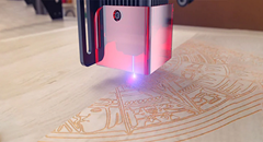
Laser engraving machines, such as Longer Ray5, are able to emit a laser beam that instantly transforms the state of matter by combustion, and the contrast between the laser-subjected surface and the surrounding surface creates the visual effect commonly called laser engraving. However, the energy hitting a single point is not limited to that point, but the heat generated is also transmitted to the areas surrounding the point causing the typical burning effect of laser processing.

In order to avoid or reduce this effect, an air assist mechanism can be used, which consists of a compressor capable of continuously blowing pressurized air directly onto the area subjected to the laser. In this way, the heat exchanged between the laser area and the surrounding area is mitigated by the fresh air of the Air Assist compressor, thus avoiding the burnt effect around the laser engraving. In addition, the air blown on the engraving zone cancels the heat exchange with the surrounding areas but does not damage the engraving ability of the laser beam. A simple example to understand this phenomenon can be this: if on a summer day with the sun high in the sky you go to the sea, if there is wind, then you feel cool, while if there is no wind, then you feel hot, but in both cases the sun causes burns to the skin in the same way.

Longer Ray5 10W has an official Air Assist kit that consists of two parts, the nozzle kit and the air compressor. Installing the Longer Air Assist is really easy; just follow the steps below:

  • First, proceed to disassemble the laser module from the rest of the machine

  • Install the metal nozzle on the laser module

  • Connect a rubber hose between the metal nozzle and the pressure regulator, and connect another part of the rubber hose to the regulator inlet

  • Connect the inlet pipe of the regulator to the outlet of the air compressor

  • Finally, install the laser module on the Ray5, activate the compressor switch and start an engraving from the Longer Ray5 display

The use of air assist not only increases the engraving quality but can also increase the laser's cutting capacity thanks to the possibility of removing smoke and combustion debris thanks to the continuous breath of air; without air assist, these would end up settling on the laser lens, hindering the output laser beam of the module. Whether for hobbyist or professional use, Longer Air Assist is absolutely recommended if you want to achieve the maximum performance offered by Longer Ray5 10W.

https://eu.longer.net/collections/laser-engraver-accessories

By Software | September 16, 2022
Item’s positioning on the printing bed

In FDM 3D Printing, during the slicing phase of the project to be printed you can completely choose how to place it on the print bed. In fact, each piece, depending on its geometry, can have one or more positions suitable for printing. The most trivial example is a full cube: whatever its side is placed on the print bed, the result does not change. Instead, the rectangle printing changes depending on the side placed on the plane, since depending on which side is placed on the plane, the printing of the rectangle can be developed in height or in length.

Another good reason to choose the correct position on the print bed is the possibility of avoiding the use of supports. In fact, for some projects it is possible to avoid cantilevered parts simply by changing the printing orientation: the final piece will be as desired, but its realization will have been much easier and faster.

However, often choosing a position without requires supports is not enough, and sometimes it is also a bad choice. In fact, depending on how the piece is printed, it takes on a different breaking point and a different load capacity. The example shown there are two positions that do not provide supports, but only one is the best one due to the geometry of the object.


In case A, the parts highlighted in green are connected to the part highlighted in black only by a single layer; therefore, by applying an orthogonal force to the parts highlighted in green, they will be easily subject to breakage.
In case B, the parts highlighted in green are connected to the part highlighted in black through many layers; therefore, wherever an orthogonal force is applied, each part will be endowed with increased strength.

Sometimes it is more convenient to choose a location that requires supports rather than a position that does not need supports. An object like the one shown in this example focuses all effort on the part highlighted in blue, so the print between the part highlighted in blue and the part highlighted in yellow must be as strong as possible.


During placement on the print bed, these two positions are usually chosen, where the first does not need supports while the second needs supports.

In case C, the parts highlighted in blue are connected to the part highlighted in yellow only by a single layer; therefore, by applying an orthogonal force to the parts highlighted in blue, they will be easily subject to breakage.
In case D, the parts highlighted in blue are connected to the part highlighted in yellow by many layers; therefore, by applying an orthogonal force to the parts highlighted in blue, each part will be endowed with greater strength. This is a case that shows that despite the presence of supports, printing will be mechanically better.

There are numerous cases where the absence of supports is an advantageous aspect, while in other cases it is absolutely necessary to carefully evaluate how to obtain a strong and durable piece regardless of whether or not you need supports. Each piece will assume a different printing configuration depending on its geometry, so it is always advisable to carefully evaluate the placement of the project on the print bed before starting a slicing, imagining the object in the context in which it will be used.

https://eu.longer.net/products/lk5-pro-fdm-3d-printer

By Software | September 5, 2022
MKSLaser - Longer Ray5 Smartphone App - LONGER
MKSLaser - Longer Ray5 Smartphone App

Longer Ray5 adopts an MKS DLC32 mainboard, characterized by wireless technology, microSD card reading, a touchscreen display with a graphic interface, and total interaction with your smartphone through the MKSLaser application.

MKSLaser is an application for Android/iOS smartphones used to interact with Longer Ray5 and allows you to move the laser within the work area, switch the laser beam on and off, define the homing position, transfer files, start an engraving, monitor engraving information, and so on. Thanks to MKSLaser, your smartphone becomes not only a remote display for Longer Ray5 but also a powerful device for processing your work.

After downloading MKSLaser, first make sure that your smartphone and Ray5 are connected to the same local network. Verify the IP address assigned to Ray5 and enter the same IP in the application. After the connection is successful, remote use can be operated.


Note: The IP address of Longer Ray5 may change frequently, so it is recommended that you set an IP RESERVATION for the Mac-Address of Ray5 within the DHCP parameters of your Router/Access Point so that you always get the same IP address at each subsequent connection.

The MKSLaser Home screen shows at the top the current X/Y coordinates and the S intensity of the laser, while at the bottom there are four large buttons to access the corresponding submenu:

  1. Creation

It allows you to process an image and slice it for engraving exactly as you do when using desktop LaserGRBL/LightBurn, in an easy and comfortable way from your smartphone.

A. Import an image or take a photograph, which can be edited in several ways

B. In the next step you can edit the image by manually setting brightness, contrast, and other effects.

C. In the last step you can configure file name change, image size, engraving speed, laser power, M3/M4 mode, and more.

D. After finishing adjusting the parameters, you can slice and upload it via WiFi to the Ray5 microSD. After Ray5 has received it successfully, you will enter the engraving page from which you can monitor the progress of the processing status, stop processing, or change the power and speed of processing.

  1. Control

It allows you to move the laser module within the processing area and different steps and speeds of movement can be set; you can also go back to homing, define a new homing position, turn the laser beam on and off, etc.

  1. Material

There are some graphic samples to be used to determine the best parameters for engraving on different materials. Once you have chosen the image to carry out the various tests, set the various parameters (refer to the "Creation" paragraph).

  1. Graving

The list of files on the microSD card inserted inside Longer Ray5 is shown, and you can select a file to engrave.

https://eu.longer.net/collections/laser-engraver

By Software | August 17, 2022
Printing Jerk calibration - LONGER
Printing Jerk calibration:Complete Beginner Guide for Better 3D Prints

Printing quality in FDM 3D printing depends on more than temperature and print speed. Motion behavior also plays a major role. Printing jerk calibration helps control how the printer reacts during movement transitions, direction changes, and layer shifts. Proper calibration can improve corner quality, reduce vibration, and help produce cleaner prints.


Table of Contents

  • What This Guide Covers
  • Quick Answer
  • Why This Process Matters
  • Before You Start
  • Step-by-Step Tutorial
  • Common Problems and Solutions
  • Tips for Better Results
  • Frequently Asked Questions
  • Final Thoughts

What This Guide Covers

This guide explains:

  • What jerk means in FDM printing
  • How jerk affects print quality
  • Recommended jerk behavior
  • Symptoms of incorrect settings
  • How to evaluate print results
  • Troubleshooting tips for beginners

Quick Answer

What is printing jerk calibration?

Printing jerk calibration is the process of adjusting how quickly your printer transitions into movement during printing operations.

For FDM printers:

  • Jerk affects direction changes and movement response
  • Recommended values generally fall between 10 mm/s and 20 mm/s
  • Rounded and swollen corners may indicate jerk is too low
  • Sharp corners with excessive vibration may indicate jerk is too high
  • Excessive values above 30 mm/s can create mechanical stress and vibration problems

Follow your printer's official specifications before changing settings.


Why This Process Matters

During printing, the printer axes move at a speed determined in slicing software and measured in mm/s. However, the printer does not instantly jump from zero to full speed.

Movement behavior depends on two factors:

  • Acceleration (mm/s²)
  • Jerk (mm/s)

Jerk can be described as the "instantaneous speed" reached when movement begins.

For example:

  • Print speed = 50 mm/s
  • Jerk = 10 mm/s

The printer does not immediately jump to 50 mm/s. Instead:

  1. Motion begins with the jerk value
  2. Speed then increases progressively through acceleration
  3. Full movement speed is eventually reached

Jerk settings affect:

  • Layer changes
  • Corner transitions
  • Direction changes
  • Movement pauses
  • Print completion time
  • Surface quality

Improper settings can create artifacts such as:

  • Ghosting
  • Ringing
  • Bulging corners
  • Excessive vibration
  • Mechanical stress

Before You Start

Requirements

Before evaluating jerk settings, prepare:

  • An FDM 3D printer
  • Slicer software
  • Access to printer firmware or slicer settings
  • A calibration print model
  • Stable printer placement

Precautions

Before changing settings:

  • Record your current settings
  • Change values gradually
  • Avoid extremely high values
  • Monitor printer movement during testing
  • Follow official machine specifications or instructions

Do not guess values outside supported ranges.


Step-by-Step Tutorial

Step 1: Understand How Jerk Works

Action

Understand that jerk represents the initial movement behavior of the printer axes.

The printer uses:

  • Speed settings
  • Acceleration
  • Jerk

to create motion.

Expected Result

You understand that movement is not immediate and that jerk influences the first stage of axis movement.

Important Notes

Although commonly referred to as an "instantaneous velocity," jerk in physics actually represents the rate of change of acceleration.

In practical printing use, it functions as a motion control parameter rather than true physical jerk.


Step 2: Enable Jerk Control If Needed

Action

The jerk value can:

  • Remain at firmware defaults
  • Be adjusted manually by enabling "jerk control" in slicer settings

Expected Result

The printer can use custom jerk settings if adjustment becomes necessary.

Important Notes

Do not change menu names or settings beyond those available in your slicer.

Follow official machine specifications or instructions.


Step 3: Use Recommended Jerk Range

Action

Use the recommended range:

10 mm/s–20 mm/s

Expected Result

The printer resumes movement efficiently during:

  • Layer changes
  • Direction changes
  • Angles
  • Printing pauses

Important Notes

This range is generally recommended to provide balanced performance during printing.


Step 4: Evaluate Printed Corners

Action

Inspect printed corners and geometry carefully.

Look for:

Rounded and swollen corners

or

Very sharp corners

Expected Result

You can determine whether adjustments are necessary.

Important Notes

Interpretation:

If corners appear:

Rounded and swollen with material

→ Jerk should be increased

If corners appear:

Very sharp and sharp

→ Jerk should be lowered

Do not make large adjustments all at once.


Step 5: Watch for Mechanical Issues

Action

Observe the printer during operation.

Check for:

  • Vibrations
  • Oscillation
  • Excessive movement
  • Mechanical noise

Expected Result

You can identify whether jerk settings are creating stability problems.

Important Notes

Very high values may create stress on the printer structure.

Values above:

30 mm/s

can potentially introduce structural issues.


Common Problems and Solutions

Problem Possible Cause Solution
Rounded corners Jerk too low Increase jerk gradually
Sharp corners with vibration Jerk too high Lower jerk gradually
Ringing or ghosting Excessive vibration Reduce movement aggressiveness
Printer shaking during movement Motion changes too aggressive Inspect settings and hardware
Long print times Extremely low jerk Adjust within recommended range
Surface artifacts after direction changes Improper movement tuning Evaluate corner behavior

Tips for Better Results

  • Change only one setting at a time
  • Save previous settings before testing
  • Watch the printer during initial layers
  • Evaluate corners rather than only flat surfaces
  • Keep belts and frame components secure
  • Use stable printer placement to reduce vibration
  • Follow official machine specifications or instructions

Community troubleshooting often shows that excessive motion changes can increase ringing and vibration artifacts.


Frequently Asked Questions

1. What does jerk mean in 3D printing?

Jerk controls the initial movement behavior of printer axes during transitions and direction changes.


2. What is the recommended jerk range?

A commonly recommended range is:

10–20 mm/s


3. Can high jerk damage a printer?

Very high values can create strong vibration and mechanical stress. Values above 30 mm/s may affect printer stability.


4. Why are my print corners rounded?

Rounded or swollen corners can indicate that jerk settings are too low.


5. Why do I see ringing or ghosting?

Ghosting often results from vibrations and aggressive movement changes. Motion settings can contribute to this issue.


6. Should I change acceleration and jerk together?

These settings work together, but changes should be performed carefully and independently when troubleshooting.


7. Is higher jerk always better?

No. Higher values may reduce print time but can increase vibration and reduce print quality.


Final Thoughts

Printing jerk calibration is an important part of motion tuning in FDM printing. While print speed and temperature often receive most attention, movement behavior strongly affects print appearance and machine stability.

A balanced jerk value helps improve:

  • Corner accuracy
  • Surface quality
  • Movement smoothness
  • Overall print consistency

When making changes, avoid extreme values and observe print behavior carefully. If specific settings are unavailable or unclear, always follow official machine specifications or instructions.

By Software | August 2, 2022
Installing Octoprint on Laptop/Tablet for 3D FDM printers - LONGER
Installing Octoprint on Laptop/Tablet for 3D FDM printers

Using an old computer to install OctoPrint on a laptop is one of the most affordable ways to upgrade your 3D printing workflow. Instead of purchasing additional hardware, you can convert an unused laptop or compatible tablet into a dedicated OctoPrint server and gain remote control, monitoring, plugins, and touchscreen functionality for your printer.


Table of Contents


Quick Answer

You can install OctoPrint on a laptop or compatible Windows-based tablet by first creating a bootable Raspberry Pi Desktop USB drive using Raspberry Pi Imager, then installing Raspberry Pi Desktop onto the target device and following the official OctoPrint setup process. Android and iOS tablets are not supported.


What This Guide Covers

This tutorial explains:

  • What OctoPrint does
  • Hardware and software requirements
  • How to prepare a bootable USB
  • How to convert an old laptop or tablet into an OctoPrint machine
  • Troubleshooting advice for beginners
  • Tips to improve long-term reliability

Why This Process Matters

Many 3D printer users want more than SD-card printing.

A properly configured OctoPrint setup for 3D printer control provides:

  • Remote print management
  • Browser-based printer control
  • Plugin support
  • Webcam monitoring
  • Touchscreen compatibility
  • File uploading over a network

Rather than buying a dedicated computer, you can reuse older hardware and create a low-cost solution. The original method is designed specifically to turn unused devices into a functional OctoPrint system.


Before You Start

Requirements

You will need:

Hardware

  • Old laptop or tablet
  • USB drive
  • Existing computer for preparation
  • Compatible 3D printer
  • Network connection

Software

  • Raspberry Pi Imager
  • Raspberry Pi Desktop ISO file
  • Official OctoPrint installation guide

Knowledge

  • Basic computer operation knowledge

The original guide recommends users have a minimum level of computer experience because setup difficulties or compatibility issues may occur.


Precautions

Before beginning:

⚠️ Android tablets are not supported.

⚠️ iOS tablets are not supported.

⚠️ The guide only works on devices originally running Windows with x86/x64 processors.

⚠️ Back up important files from the laptop or tablet before installation.

⚠️ Installing a new operating system may erase existing files.

⚠️ Follow official machine specifications or instructions.


Step-by-Step Tutorial

Step 1: Install Raspberry Pi Imager on a Different Computer

Action

Use a computer other than the one you plan to convert into an OctoPrint machine.

Install Raspberry Pi Imager:

Raspberry Pi Imager

Expected Result

Raspberry Pi Imager installs successfully and launches normally.

Important Notes

Raspberry Pi Imager will be used to create a bootable USB installation drive.


Step 2: Download Raspberry Pi Desktop ISO

Action

Download the Raspberry Pi Desktop ISO file:

Raspberry Pi Desktop ISO

Expected Result

The ISO file downloads completely.

Important Notes

The guide specifically uses the graphical desktop version of Raspberry Pi Desktop.

Do not substitute other files unless official instructions specify otherwise.


Step 3: Create a Bootable USB Drive

Action

  1. Insert the USB drive into your computer.
  2. Open Raspberry Pi Imager.
  3. Click:

"Use Custom Image"

  1. Select the downloaded ISO file.
  2. Create the bootable USB drive.

Expected Result

The USB drive becomes a bootable installation device.

Important Notes

Wait for the process to finish completely before removing the USB drive.

Interrupting the writing process can cause installation failures.


Step 4: Insert the Bootable USB into the Target Laptop or Tablet

Action

Move to the laptop or tablet you want to convert.

Insert the prepared bootable USB drive and begin installing the Raspberry Pi Desktop operating system.

Expected Result

The laptop or tablet starts the Raspberry Pi Desktop installation process.

Important Notes

Only Windows-based x86/x64 hardware is supported in this guide.


Step 5: Install OctoPrint Using the Official Setup Guide

Action

After Raspberry Pi Desktop installation finishes, follow the official OctoPrint setup guide:

Official OctoPrint Setup Guide

Expected Result

Your laptop or tablet becomes a working OctoPrint system.

Important Notes

Do not skip official instructions.

Follow the setup sequence exactly as provided.


What Happens After Installation?

Once completed, your converted system gains features similar to an OctoPrint Raspberry setup:

  • Plugin compatibility
  • Touchscreen interaction
  • Remote printer monitoring
  • Camera integration
  • Browser access

If using a touchscreen tablet, you can interact directly with the OctoPrint interface through touch controls.


Recommended Related Guides

If you are improving your printer workflow, these resources can help:


Common Problems and Solutions

Problem Requirements Solution
USB drive not detected Proper USB connection Reinsert USB drive and recreate the bootable media
Device does not boot from USB Boot access available Verify boot settings on the device
Raspberry Pi Desktop installation fails Stable installation media Recreate the bootable USB
OctoPrint inaccessible Network available Follow the official OctoPrint instructions
Touchscreen not responding correctly Compatible hardware Follow official machine specifications or instructions
Printer communication issues USB connection Verify printer connection and settings

Tips for Better Results

1. Use dedicated hardware if possible

Avoid running unrelated heavy software on the same machine while printing.

2. Keep the device powered continuously

Unexpected shutdowns can interrupt active prints.

3. Enable camera monitoring

A webcam can help monitor print progress remotely.

4. Keep software updated

Use official updates whenever available.

5. Use plugins carefully

Too many plugins may increase resource usage.


Frequently Asked Questions

Q: How to install OctoPrint on an old laptop?

A: Install Raspberry Pi Imager on another computer, create a bootable Raspberry Pi Desktop USB drive, install Raspberry Pi Desktop onto the old laptop, and follow the official OctoPrint setup guide.


Q: Can I install OctoPrint on Android tablets?

A: No. Android-based tablets are not compatible with this method.


Q: Can I install OctoPrint on iPads?

A: No. iOS devices are not supported by this setup method.


Q: What processor type is required?

A: The guide works on laptops and tablets originally designed for Windows using x86/x64 processors.


Q: Is a Raspberry Pi required?

A: No. This guide specifically uses a laptop or tablet as an alternative solution.


Q: Can I use touchscreen functionality?

A: Yes. A compatible tablet can interact with OctoPrint through touch controls after setup.


Q: Can I monitor prints remotely?

A: Yes. Camera functionality can be implemented for remote monitoring.


Final Thoughts

Learning how to install OctoPrint on a laptop is an effective way to upgrade a 3D printing workflow without purchasing dedicated hardware. By reusing an old laptop or compatible tablet, you can gain remote control, touchscreen interaction, plugin support, and monitoring capabilities while extending the life of older devices.

For additional setup information and advanced functionality, continue exploring related 3D printing tutorials and official support resources.

By Software | July 28, 2022