Blobs in 3D Printing - LONGER
Blobs in 3D Printing

Many users of 3D printing, regardless of their experience, often find themselves facing an annoying problem that is really difficult to eliminate: blobs on the outer surface of the prints. This phenomenon often appears suddenly, only on particular prints, even when you think you have found the perfect Slicer settings for optimal print quality. So we proceed with varying the temperature, the speed, the accelerations, etc., but despite this the problem is not solved, but only a little attenuated.

Blobs are deposits of molten material along the outer surface of a print, take on the appearance of "little balls" and are difficult to remove even by handworking the print in post-production. These occur when the nozzle abnormally releases molten material, and often this is independent of slicer settings such as retraction and flow.

When math is indispensable for 3D printing

In geometry, a polygon takes on a different name and appearance based on its number of sides (segments). In particular, a polygon composed of 3 segments will be called a triangle, composed of 5 segments will be called pentagon, 6 hexagon segments, 10 decagon segments, ..........., from 1.000.000.000 segments will be something very similar to a circumference, from 1.000.000.000.000 segments will look almost a circumference, from 1.000.000.000.000.000.000 segments will be practically a circumference.

Thus, a polygon of n-sides, with very large n and each segment very small, can be approximated with a circle, with greater precision as nincreases. This technique is used by 3D printers to print a circumference, transforming it into a series of XY coordinates of n segments, with n more or less large depending on the number of meshes of the original stl model. Thus, a circumference is a series of countless segments, each of very small amplitude, made one after another on the hotbed of the 3D printer.

However, what to the eye seems to be a very simple circumference, actually requires a high computational cost for the mainboard of the 3D printer, as it is necessary to process in a fraction of a second millions of coordinates of millions of segments. In addition, depending on the number of meshes of the original stl model, 3D printing may often have to process much more data than is sufficient to achieve a perfect circumference, sometimes even more than its hardware capacity in terms of resolution.

Therefore, if for example the 3D printer can realize a perfect circumference starting from 10.000.000.000 segments, and this is also its maximum resolution, when its mainboard is found to process 1.000.000.000.000.000 segments this will perform unnecessary work, both because it is possible to obtain an optimal result with a lower computational cost and because such processing cannot be put into practice due to the hardware limitations of an FDM printer.

Correlation between geometry and blobs

As seen above, for a simple circumference, a 3D printer is faced with a very complex calculation in no time, often a calculation even greater than necessary. So it can happen that the mainboard cannot process the data in time, so the hardware not receiving print coordinates can only stop. These stops occur for a very short time, almost imperceptible, but they are enough for the nozzle to lose molten material along the outer perimeter of printing, thus forming a blob.

Therefore, regardless of one's slicing settings, the blobs phenomenon cannot be solved easily as it is dependent on the type of 3D drawing, its number of meshes, the original designer's ability to make it, and the computational ability of the mainboard of your 3D printer.

Resolve the problem

The optimal approach to solve this problem would be to manipulate the stl file in question, going to reduce the number of meshes, repair it and try to reduce its size in terms of megabytes. However, this operation often turns out to be complex, suitable only for experts, or even impossible.

On the other hand, the Ultimaker Care slicer is equipped with a special, hidden feature that not everyone knows about, which is very useful for reducing the number of meshes of a 3D object. This option is called "Mesh Fixes" and is intended to reduce the number of meshes of an object by varying the maximum length of each segment. In this way, by increasing the maximum distance of each segment, at the same perimeter inevitably the number of segments must be smaller, and therefore the computational cost of the mainboard is also reduced. Therefore, by processing the gcode more easily, the 3D printer will be able to process a greater number of displacements without suffering from pauses, and therefore reducing the blobs.


In particular, by changing the default settings with the values above it will be possible to solve almost entirely the problem of blobs, without altering the standard FDM print quality. It should be considered in mind that professional 3D printers, such as FDM Ultimaker printers, adopt by default values of 0.7 mm without affecting their ability to make details and resolution.

If after changing the parameters in question should still persist some sporadic blobs, it will be possible to totally solve the problem by slightly adjusting the values of temperature and downward flow, the upward retraction. Alternatively, you can always increment the Mesh Fixes values at the expense of details.

The print difference with the standard and custom Mesh Fixes settings are immediately visible:

Both tests were done keeping the exact same slicing settings for both, except for varying the Mesh Fixes values.

The test stl file has been modified, damaged and repaired three times, in order to make it difficult for the mainboard to be processed.

https://eu.longer.net/products/lk5-pro-fdm-3d-printer

By Software | June 16, 2022
Cyclonic Separator - LONGER
Cyclonic Separator

After completing the calibration of your 3D printer, following the previous articles of the Longer 3D Academy, you can check the results obtained through the test below.

The object that we are going to print is a "Cyclonic Separator", that is a particular object that is placed between the vacuum cleaner and the suction pipe, and which allows you to separate up to 99% of the dirt present in the suction pipe. In this way the vacuum cleaner will always remain clean and above all its filters will not freeze; so this object turns out to be extremely useful when you intend to vacuum the residues produced by woodworking, the fine dust produced by the processing of 3D prints, the residues produced by laser cutting, and so on.

Printing the Cyclone requires that the printer has been perfectly calibrated, otherwise the print will not be perfect and will not guarantee the promised results. Therefore, if the printer is ready, here's how to proceed.

The model consists of the main body of the cyclonic separator and two input and output adapters, which serve as a connection between the cyclone and the vacuum cleaner pipes. For best results it is recommended to use PETG, however if you do not have some experience with this material then you can also use PLA.


To make the connection more stable, it is possible to put a little rubber insulating tape around the adapters, so as to have more stable and sealed joints. In addition, the Separator will need a container compatible with its screw attachment, and an easily accessible example is a classic transparent bottle of Coca-Cola or any other container with a similar thread.

Once the Cyclonic Separator is installed as shown in the figure, almost all the sucked dirt will go inside the bottle instead of inside the vacuum cleaner, thus avoiding clogging the filters with fine dust.
Remember never to put your hand in front of the suction, as the Cyclonic Separator works on pressure differences; therefore, obstruction of the suction will cause the container to implode!
This video shows the Cyclonic Separator in action: https://youtu.be/FEvztl8UPPk

https://eu.longer.net/collections/accessories

By Software | June 16, 2022
Transform a 2D image into a 3D model - LONGER
Transform a 2D image into a 3D model

Turning a flat image into a printable 3D object is one of the most exciting entry points into 3D printing. In this beginner-friendly guide, you will learn how to transform a 2D image into a 3D model using a simple workflow that prepares your image for 3D printing and STL export.

Whether you want to create personalized decorations, lithophanes, signs, or artistic relief models, this tutorial walks you through the complete process step by step.


Table of Contents


Quick Answer

To transform a 2D image into a 3D model, you first prepare a high-contrast image, import it into compatible 3D software, convert it into a height map or relief model, then export the final result as an STL file for 3D printing.

This method is commonly used for lithophanes, engraved artwork, decorative panels, logos, and custom gifts.


What This Guide Covers

This tutorial explains:

  • How to prepare an image for 3D conversion
  • How height maps create 3D depth
  • How to generate an STL file from a 2D image
  • How to prepare the model for 3D printing
  • Common troubleshooting methods
  • Beginner tips for achieving cleaner results

By the end of this guide, you will understand the full workflow required to create a 3D printable model from a flat image.


Why Transform a 2D Image Into a 3D Model

Converting a 2D image into a 3D model opens up many creative possibilities for makers, designers, hobbyists, and small businesses.

Benefits include:

  • Creating personalized gifts
  • Producing custom lithophanes
  • Designing engraved wall art
  • Turning logos into printable objects
  • Making relief sculptures from photos
  • Creating decorative nameplates and signs

This process is especially useful for users who are new to 3D modeling because it reduces the need for advanced CAD design skills.

If you are also learning laser engraving workflows, you may find it helpful to explore related tutorials from LONGER Official Website.


Before You Start

Requirements

Before starting the 2D to 3D model tutorial, prepare the following:

Hardware

  • A computer capable of running 3D modeling software
  • A 3D printer (optional for physical printing)

Software

  • Image editing software
  • 3D model generation software
  • Slicing software for STL preparation

Follow official machine specifications or instructions.

Recommended Image Types

Best results usually come from:

  • Black-and-white images
  • High-contrast graphics
  • Logos
  • Portraits with clear lighting
  • PNG or JPG files

File Types

Common export formats include:

  • STL
  • OBJ

Precautions

Before converting an image to a 3D model, keep these important points in mind:

Use High-Contrast Images

Low-contrast images may create uneven or unclear depth details.

Avoid Excessive Background Detail

Busy backgrounds can generate unwanted surface noise in the final model.

Check Image Resolution

Very small images may appear pixelated after conversion.

Verify Printable Thickness

Thin model sections may fail during 3D printing.

Follow Official Printer Settings

Always follow official machine specifications or instructions when preparing print settings.

For additional print preparation guidance, you can review the slicing tutorials available on LONGER Support Center.


Step-by-Step Tutorial

Step 1: Prepare Your 2D Image

Action

Choose and prepare the image you want to convert into a 3D model.

The image should be:

  • Clear
  • High resolution
  • High contrast
  • Properly cropped

If necessary, remove unnecessary background elements and improve contrast using image editing software.

Expected Result

You should have a clean image that clearly separates light and dark areas.

Important Notes

  • Black areas are often interpreted as lower regions.
  • White or brighter areas are often interpreted as higher regions.
  • Complex gradients may create uneven surfaces.

If you are creating engraved artwork, you may also benefit from reading image optimization tutorials on LONGER Academy.


Step 2: Import the Image Into the Software

Action

Open your chosen 3D generation software and import the prepared image file.

Most software tools provide an image import or height map function that converts brightness values into elevation data.

Expected Result

The software should display the imported image and prepare it for 3D conversion.

Important Notes

  • Ensure the image is correctly oriented before generating the model.
  • Some software may automatically invert brightness values.
  • Double-check preview settings before continuing.


Step 3: Convert the Image Into a Height Map

Action

Use the software’s height map or relief generation feature to convert the 2D image into 3D geometry.

The brightness of the image determines the depth of the generated surface.

Expected Result

A preview of the raised or recessed 3D surface should appear.

Important Notes

  • Higher contrast usually produces clearer depth separation.
  • Excessively detailed images may generate rough surfaces.
  • Small adjustments can significantly affect the final appearance.

Understanding Height Map Conversion

A height map converts brightness into physical depth:

  • White areas = higher surfaces
  • Black areas = lower surfaces
  • Gray areas = intermediate depth

This is one of the most common methods used to create a 3D model from an image.


Step 4: Generate the 3D Model

Action

Generate the final 3D mesh after adjusting the model settings.

Inspect the model carefully in preview mode.

Expected Result

The software should create a complete 3D object that can be rotated and inspected.

Important Notes

Check for:

  • Broken geometry
  • Missing sections
  • Uneven surfaces
  • Thin walls

If problems appear, return to the image preparation stage and improve contrast or simplify the design.


Step 5: Export the STL File

Action

Export the completed model as an STL file.

STL is the most commonly used format for 3D printing workflows.

Expected Result

You should obtain a printable STL file ready for slicing.

Important Notes

  • Save backup project files before exporting.
  • Confirm the export scale before printing.
  • Check the model dimensions carefully.

Step 6: Prepare the File for 3D Printing

Action

Import the STL file into slicing software and configure the print settings.

Adjust:

  • Layer height
  • Infill
  • Supports
  • Orientation

Follow official machine specifications or instructions.

Expected Result

The slicer should generate a printable G-code file.

Important Notes

  • Model orientation can greatly affect print quality.
  • Thin models may require supports.
  • Larger relief designs may increase print time significantly.

If you are new to print preparation, you can also explore additional beginner resources from LONGER 3D Printing Guides.


Common Problems and Solutions

Problem Requirements Solution
Image lacks detail High-resolution source image Use a clearer and larger image
Surface appears rough Proper contrast adjustment Simplify the image and reduce noise
Model contains holes Clean geometry Recheck image preparation and regenerate
STL file will not slice Valid mesh structure Repair the mesh using mesh repair tools
Print fails during printing Stable print settings Verify adhesion and follow official machine specifications
Depth looks inverted Correct brightness interpretation Invert the image colors before conversion
Details are too shallow Proper height settings Increase height map depth gradually

Tips for Better Results

Use Simple Images First

Beginners should start with logos or black-and-white graphics before attempting detailed portraits.

Increase Contrast Carefully

Higher contrast improves depth separation but excessive contrast can remove subtle details.

Avoid Tiny Features

Very small elements may not print correctly depending on nozzle size and layer height.

Preview the Model From Multiple Angles

Always rotate and inspect the model before exporting the STL file.

Test Print Small Versions First

Printing a smaller prototype can save time and material before creating the full-size model.


Frequently Asked Questions

Q: How do you transform a 2D image into a 3D model?

A: You import a high-contrast image into 3D software, generate a height map or relief surface, then export the result as an STL file for 3D printing.


Q: What is the best image type for converting to a 3D model?

A: High-contrast black-and-white images usually produce the cleanest and most detailed results.


Q: Can I convert a photo into a 3D model for beginners?

A: Yes. Beginner-friendly tools can convert photos into relief-style 3D models using grayscale depth mapping.


Q: What file format is used for 3D printing?

A: STL is the most commonly used file format for preparing 3D printable models.


Q: Why does my 3D model look rough or noisy?

A: Low-quality images, excessive detail, or poor contrast can create rough surfaces during height map conversion.


Q: Can I make a lithophane from an image?

A: Yes. Lithophanes are commonly created by converting grayscale images into varying thickness levels for 3D printing.


Q: Do I need advanced CAD skills for a 2D to 3D model tutorial?

A: No. Many image-to-3D workflows are beginner-friendly and require minimal CAD experience.


Q: What is the best way to create a 3D model from a 2D image?

A: Start with a clean, high-contrast image and use reliable 3D conversion software that supports height map generation.


Final Thoughts

Learning how to transform a 2D image into a 3D model is an excellent way to begin exploring 3D printing and digital fabrication. With the right image preparation and careful workflow setup, even beginners can create impressive relief models, lithophanes, logos, and decorative prints.

Start with simple designs, test your settings carefully, and continue refining your workflow as you gain experience. For additional tutorials, troubleshooting help, and machine-specific guides, explore the resources available on LONGER Official Blog.

By Software | June 16, 2022
Transform a 3D model into a 2D image - LONGER
Transform a 3D model into a 2D image

If you work with laser engravers or digital fabrication tools, you often need to transform 3D model into 2D image formats like PNG or SVG. This is because most laser engraving software only supports flat image inputs. In this guide, you’ll learn how to easily convert a 3D model into a 2D image using built-in Windows tools.

This workflow is especially useful for beginners who want a fast, no-plugin method for preparing engraving-ready files.


Table of Contents


Quick Answer

To transform a 3D model into 2D image, open your model in Paint 3D, adjust the viewing angle if needed, then use “Menu → Save as → Image” and export it as a PNG file. Enable the transparency option before saving for laser engraving use.


What This Guide Covers

This tutorial explains how to:

  • Import a 3D model into Paint 3D
  • Adjust camera angle and framing
  • Export a clean 2D image from a 3D object
  • Save the output as a transparent PNG
  • Use the exported image in laser engraving software

By the end, you’ll be able to convert almost any 3D model into a usable 2D file for engraving or design workflows.


Why This Process Matters

In laser engraving and CNC workflows, input files are always 2D formats such as PNG, JPG, or SVG. However, many design assets begin as 3D models.

Converting a 3D model into a 2D image allows you to:

  • Prepare engraving-ready designs quickly
  • Capture realistic views of 3D objects
  • Simplify complex models into flat artwork
  • Improve workflow efficiency for LightBurn or LaserGRBL

This method bridges the gap between 3D design and 2D fabrication output.


Before You Start

Requirements

  • Windows 10 (or later)
  • Paint 3D preinstalled (or downloaded from Microsoft Store)
  • A 3D model file (compatible format supported by Paint 3D)

Precautions

  • Ensure your 3D model is properly scaled before exporting
  • Check that the model is fully loaded before saving
  • Avoid extremely complex models that may slow down rendering

If Paint 3D is unavailable on your system, follow official machine specifications or instructions.


Step-by-Step Tutorial

Step 1: Open Paint 3D and Import Your Model

  • Action: Open Paint 3D software preinstalled in Windows 10. Then select Open and import your 3D file.
  • Expected Result: Your 3D model appears in the workspace and is ready for editing.
  • Important Notes: Ensure the file format is supported; otherwise, the model may not load correctly.

Step 2: Load the 3D Model into the Workspace

  • Action: Select the option to open the 3D file and wait for it to fully load.
  • Expected Result: The model becomes interactive, allowing rotation and viewing from different angles.
  • Important Notes: Large models may take longer to load; do not close the software during processing.

Step 3: Adjust Angle & Framing (Optional)

  • Action: Press “Adjust Angle & Framing” if you want to modify the viewing angle.
  • Expected Result: The camera view changes, letting you select the best perspective for your image.
  • Important Notes: Choose an angle that best represents the model for engraving clarity.


Step 4: Save as Image

  • Action: Go to Menu → Save as → Image.
  • Expected Result: A save dialog appears allowing you to choose image format options.
  • Important Notes: This step converts your 3D view into a 2D snapshot.

Step 5: Enable Transparency and Export PNG

  • Action: Enable the checkbox for Transparency, then save the file as a PNG image.
  • Expected Result: A clean 2D image with a transparent background is generated.
  • Important Notes: Transparency is critical for laser engraving workflows.

Step 6: Use the 2D Image in Laser Software

  • Action: Import the exported PNG into software like LaserGRBL or LightBurn.
  • Expected Result: The image is ready to be converted into G-code for engraving.
  • Important Notes: Ensure contrast is strong enough for engraving visibility.


Common Problems and Solutions

Problem Requirements Solution
Model does not load Unsupported file format Convert model to compatible format before importing
Image has no transparency Transparency not enabled Re-export and check “Transparency” option
Poor image quality Low resolution export Re-save at higher quality settings if available
Wrong viewing angle Camera not adjusted Use “Adjust Angle & Framing” before exporting
File not usable in laser software Incorrect format Ensure output is saved as PNG

Tips for Better Results

  • Choose a clear and simple viewing angle for engraving clarity
  • Use high-contrast models to improve laser visibility
  • Avoid overly complex geometry when possible
  • Always preview the image before exporting
  • Test engraving on scrap material first

These small adjustments significantly improve final engraving quality.


Frequently Asked Questions

Q: What does transform 3D model into 2D image mean?

A: It means rendering a 3D object into a flat image (like PNG) that can be used in 2D software such as laser engraving tools.


Q: Can I use any 3D file format?

A: Only formats supported by Paint 3D can be used. If a file fails to load, convert it first.


Q: Why do I need a transparent background?

A: Transparency ensures clean engraving paths without unwanted background artifacts.


Q: Can I change the angle after exporting?

A: No. You must adjust the angle before saving the image.


Q: What software can use the exported image?

A: LaserGRBL, LightBurn, and similar laser engraving programs support PNG files.


Q: Is Paint 3D required?

A: Yes for this method. Otherwise, follow official machine specifications or instructions for alternative workflows.


Q: Can I batch convert multiple models?

A: Paint 3D does not support batch exporting. Each model must be processed individually.


Final Thoughts

Converting a 3D model into a flat image is a simple but powerful workflow for laser engraving users. By using Paint 3D’s built-in export tools, you can quickly transform 3D model into 2D image files without complex software.

This method is ideal for beginners and ensures compatibility with most engraving platforms like LightBurn and LaserGRBL. For more advanced workflows, explore additional tutorials on model optimization and engraving calibration.

By Software | June 16, 2022
How to upgrade LONGER LK4 PRO into a mini-LK5 PRO - LONGER
How to upgrade LONGER LK4 PRO into a mini-LK5 PRO

Our Longer LK4 PRO and LK5 PRO 3D Printers are very similar, but the differences between them are not limited only to the different printing area, but on the LK5 PRO there are other small improvements that make this printer much superior to LK4 PRO.

However, if you already own an LK4 PRO and do not intend to buy LK5 PRO as well, here is a series of tips to make your LK4 PRO like a mini-LK5PRO, thus improving its printing capacity and hardware structure.

1) Hotbed Cable Bracket Holder

The LK4 PRO has a Hotbed power cord simply connected via a clip-on connector. This, as a result of repeated movements during printing, may disconnect, bend or break; for this reason it is really important to install a cable bracket that makes the connection fixed, exactly as for LK5 PRO. About that:

  1. Download the official Bracket Longer: https://www.thingiverse.com/thing:4818795
  2. Print it using 0.1mm Layer Height & 100% Infill as recommended settings
  3. Proceed to the installation as follows:
    • Unscrew and remove the 4 leveling knobs, remove the hotbed
    • Place the bracket on the metal plane, place the leveling spring in the bracket compartment
    • Assemble the hotbed again and screw in the 4 leveling knobs
    • Attach the cable to the Bracket using two fixing clamps
  4. Here is the final result:

2) Mainboard fan protection grid

The LK4 PRO's mainboard fan does not have a protective grid like that of the LK5PRO, so if you don't have a compatible metal grid then you can install a printed one. About that:

  1. Download the official Longer mainboard grid:

https://www.thingiverse.com/thing:4957827

  1. Print it using 0.1mm Layer Height & 100% Infill as recommended settings
  2. Proceed to the installation as follows:
    • Unscrew the 4 mainboard fan screws
    • Place the grid
    • Start the 4 screws
    • Note: Due to the grid, you need to use 4 screws longer than the originals
  3. Here is the final result:

3) Spool Holder on the side

The LK4 PRO printer provides for the installation of the Spool Holder at the top; however, if you prefer to install the Spool Holder on the side of the printer, as for LK5 PRO, here is a practical upgrade to print and install easily:

  1. Download the official Longer bracket for Spool Holder: https://www.thingiverse.com/thing:4957817
  2. Print it using 0.2mm Layer Height & 100%Infill as recommended settings
  3. Proceed to the installation as follows:
    • Attach the original Spool Holder to the Bracket, using two bolts of correct size
    • Attach the bracket to the printer using at least two T-Nuts
  4. Here is the final result:

4) Ultrabase Plate in Micro-perforated Latex

Differently from LK5 PRO, which is equipped with a Micro-perforated glass plate, LK4 PRO has a glass plate covered with a rough ceramic film, excellent for having a perfect print adhesion, however it may often be difficult to remove the prints from the glass, as the adhesion remains unchanged even with a cold plate.

For this reason, it could be a good solution to proceed with the installation of a Micro-perforated glass plate also on the LK4 PRO, so as to obtain excellent adhesion during printing and easy removal of prints from the cold plate. In fact, the Longer Micro-perforated Latex plate is equipped with micropores, which with heat (starting from 60 °C) it "sticks" to the first printing layer, thus ensuring excellent adhesion as long as the plate remains hot. At the end of printing, cooling the micropores gradually it releases the printed surface, so the printed object will simply be placed on the plate and can be easily removed.

This upgrade can be got really easily, as it can be purchased at all our official Longer stores, at a very low price:

Once you install all these upgrades, your LK4 PRO will be like a mini-LK5 PRO!
Our guide ends here, but if you need more spare parts or would like to make extra upgrades, then do not hesitate to contact us on our Official Longer Facebook pages or at our email address: support@longer3d.com

https://eu.longer.net/products/lk5-pro-fdm-3d-printer

By Software | June 16, 2022
LONGER LK5 Pro Full Use Tutorial: Assembly&Setup Instruction

First of all

LONGER LK5 PRO firmware download: https://drive.google.com/drive/folders/1xvMYLhAvwqhYiqoT559U8gBzruGjQ_AE?usp=sharing

1. About LK5 PRO install steps

If you find it lost, please contact our technical team at support@longer.net; after confirmation, we will resend the new part to you.

We make video tutorials about installation steps; please follow:

https://www.youtube.com/watch?v=F_VzVxOhHSo

About LK5 PRO install steps

2. First turn on

The touch screen is not bright


Confirm whether the input voltage range of the switching power supply is consistent with the electricity voltage in the area and the screen cable is connected.
If still does not work, check the power indicator and the mainboard indicator (method: remove the bottom mainboard protective cover; refer to the video in the link below.)

https://www.youtube.com/watch?v=K8Jwu-faDfQ

Fan noise and abnormal sound.


Make sure that the fan blades are not damaged and that there are no foreign objects. You can email fan photos to support@longer.net help you confirm.

3. Leveling bed

The distance between the hot end nozzle and the hot bed is 0.1-0.2 mm. follow below video leveling bed: https://www.youtube.com/watch?v=TJ0MOFPuOTQ. If it still can't be solved, put the hot bed glass and aluminum substrate on a flat table to check whether there is bending, if the bed bending, contact LONGER 3D technical team: support@longer.net

4. Zeroing failed

Failed to return to zero/abnormal noise of return to zero/impact limit still does not stop motion. Please check whether the limit switch is complete and the installation condition, and follow the video: https://www.youtube.com/watch?v=m3sQGZVFDqY., check the cable installation condition.

About the Z-axis limit switch height adjustment, refer to the video in the link below.
https://youtu.be/F_VzVxOhHSo?t=255

5. Load/unload filament

Error8

Check the real-time hot-end temperature display on the screen. If it is negative, check the installation of the thermistor plug; make sure it is installed as below:

check the installation of the thermistor plug

If anything good about thermistor, that is hot end issue, in this case we should follow the below video to change hot end: https://www.youtube.com/watch?v=RwpLTFwFzAg

Error0 or Error12

Check the installation of the hot-end thermistor and the plug of the hot-end heating rod.
If the installation is normal, the cable may be broken. Replace the hot end;

The extruder is not working

  1. Check the installation of the extruder cable plug (E refers to the extruder).
    2. The extruder defaults to work after reaching the hot end set temperature (minimum 195 degrees). If it still cannot work, check the installation of the extruder motor wire.
    3. If it still can't work, exchange the X and E motor wire plugs, control the movement respectively, and report the situation to the after-sale service.

Filament cannot be extruded

When, without loading the filament, the extruder works fine, this situation is a hot end block. When the filament is not loaded, the extruder works abnormally; please contact the after-sales service directly support@longer.net

Nozzle smoking

Check the thermistor is completely detached or loosely installed (check when cooling); reinstall it.

6. Start printing

If LK5 PRO printer does not recognize the Micro SD card file


Use a tool to format the Micro SD card and reload the file.
Micro SD Card Formatting Software
https://drive.google.com/drive/folders/1TgCT1CBsjI4-7prSu1nEUXxQ6vhsJzms?usp=sharing
Micro SD card preload file download address
https://drive.google.com/drive/folders/1zz5mlLMBoa3DguuyG6YDHJJXnhL-XKnJ?usp=sharing
Dip the SD card in alcohol, pull out and insert it into the SD card slot several times. Wait for the alcohol to evaporate completely, and restart the machine to check whether it works again.

If still not work, contact LONGER 3D technical team: support@longer.net


Newly added files not recognized


LONGER LK5 PRO recognizes the Gcode file in the root directory of the Micro SD card and checks the format of the newly added file.
P.S. Gcode files can be generated by slicing software.
If still not work, contact LONGER 3D technical team: support@longer.net.


Error 9


Check that the touch screen displays the real-time hotbed temperature, and if it is negative, check the installation of the hotbed cable plug.
The cable is installed normally. Use a multimeter to check the resistance of the aluminum substrate.
video about measure the resistance of the hot bed socket: https://www.youtube.com/watch?v=yFV3JCilzA8

If still not work, contact LONGER 3D technical team: support@longer.net


Error 1/13


Check the heatbedcable plug installation.
Check the resistance of the aluminum substrate. If it is normal, replace the cable for testing. If the cable is still abnormal, contact LONGER 3D technical team: support@longer3d.com

The print size is too small


Check the computer slicing software to set the print format.
If this does not resolve, check the printer firmware information.
PS: LK5 Pro firmware and update guide files can be downloaded at the link:

https://drive.google.com/file/d/1rRos32XckF5ZlI5tYlCTlyt22E_BlQXP/view?usp=sharing.

LONGER LK5 PRO 3D printer firmware upgrade in this article:

https://eu.longer.net/blogs/academy/longer-lk5-pro-full-use-tutorial Filament not sticking to platform

Check whether the slicing software parameters are the default parameters of the Cura Longer machine, and try to relevel (the proper distance between the nozzle and the printing bed is the thickness of a sheet of A4 paper). For leveling the bed, check the video in the link below.
https://www.youtube.com/watch?v=TJ0MOFPuOTQ
After leveling bed, add "ralf" while slicing the model
If still not work, please check, Check if the heat bed is bent in 3, Leveling bed

Filament not extruded


1. When the motor shaft of the extruder rotates, the engagement gear does not rotate; install the engagement gear fixing screw.
2. If the extruder does not work, switch the motor test; refer to the video.
https://www.youtube.com/watch?v=XCjrieoyZ1c
3. If the distance between the hot end nozzle and the hot bed is too close, relevel it.
4.
If the hot end is blocked, replace the hot end. Refer to 5.4 for the inspection method.

7. Other issue

Wrong firmware


Download the LK5 Pro firmware and update the guide file and update the firmware:
https://drive.google.com/file/d/1rRos32XckF5ZlI5tYlCTlyt22E_BlQXP/view?usp=sharing
Refer to 6.5.

During the printing process

If the power input is normal, it still display "Resume printing." In this situation, please update the firmware to the Marlin 2.0 version. the following is the firmware download link:
https://drive.google.com/file/d/10mY1k7CIIJYEa2HbqzdXNSre7h4x6Zfa/view?usp=sharing

Refer to the link below for the firmware update tutorial.
https://eu.longer.net/blogs/academy/longer-lk5-pro-full-use-tutorial
After updating the firmware, the problem still cannot be solved; contact LONGER 3D technical team at support@longer.net

bending, After the printer turned on, the touch screen is stuck on the boot page, and the firmware cannot be loaded, please confirm the touch screen cable is connected situation, if cable not issue, please contact LONGER 3D technical team: support@longer.net

By Software | February 24, 2022
How to Use 3D Printers to Print a Gift on Valentine’s Day - LONGER
How to Use 3D Printers to Print a Gift on Valentine’s Day

For centuries, Valentine’s Day has been an important day for millions of couples all over the globe. As soon as February begins, you see stores decorated with red heart balloons, teddy bears, and other Valentine's Day themed goodies. Finding a gift on Valentine’s Day for a loved one that's unique can be a little complicated. You might get lost going through multiple stores in an attempt to find something meaningful for your significant other. After all, the day is meant to be a symbol of your love.

You might have the perfect dinner planned at the best restaurant in town, but the gift is the real star of the show that they will cherish forever. Gifts are essential on Valentine's Day, just as it is on a birthday or any special occasion. However, the difference here is the meaning attached to the day. Valentine's Day gifts are practically your way of saying how much you love your significant other. It is a gift that they will cherish for years to come and consider a symbol of your love. The question then is how to give innovative and unique gifts. If you need some help, we've got great Valentine’s Day gift ideas for you.

Try Out a 3D Printer:

When it comes to Valentine’s Day gifts for her, we’re sure a personalized gift will be considered extra special. Think about a gift that you created on your own that was executed to perfection. Even if you feel as if you are unartistic or can’t draw well, a 3D printer can do all of that for you! Since it is a technological innovation that creates a physical object from s picture, it’s a great way to make Valentine’s Day gifts for him too.

All you need to do is get your hands on a 3D printer, and you can make new fantastic gifts on many Valentine's Days. The great thing about these is that there are no limits to what you can create. It's left to your imagination. It could be an inside joke, the place you met, a little keepsake, or even a big centerpiece.

What Can 3D Printers Do?

If you don't know much about 3D printers, then you're in for a surprise. These phenomenal devices can create a three-dimensional object from an image using CAD (computer-aided design). It works somewhat like ordinary printers but with a twist. Instead of using ink and paper, a 3D printer uses a material of your choice, such as plastics, composites, or biomaterials, to create the image that you instructed it to create.

For example, if you wanted to create a little figurine of a boat out of plastic, you just load a roll of plastic up into the printer. It will melt it and place it in a way that will create the figurine that was selected. You can create this image in any software as long as it is a 3D image. It does so by layering the materials that you selected to objects of any shape, size, rigidity, and color.

A Great 3D Printer:

How to Use 3D Printers to Print a Gift on Valentine’s Day

If you're interested in this excellent method to make Valentine's Day gifts, a great option is the LK5 Pro FDM 3D Printer from the trusted company LONGER 3D. This is one of the many 3D Printers that are available from LONGER, which has had multiple successful customers in the past. Moreover, now the Love Season Sale of LONGER has a huge discount. Here are some features of the LK5 Pro:

  • Assembly and structure:

The LONGER LK5 Pro is one of the printers that comes mostly preassembled. It is incredibly annoying to put one together from scratch, but this one is much easier. It is an affordable 3D Printer that is 90% preassembled. It has a printing structure of 300*300*400 mm, which is pretty great for your Valentine's Day gifts. Its dual inclined rods, along with the stable triangular structure, hold all three axes steadily in place.

  • Glass bed:

The bed of the printer is immensely important. It needs to have enough friction for the project to stay in place during printing but be smooth enough to peel off once it is complete. The LK5 Pro has a glass bed coated with ceramic. This allows for both steadiness during printing and eases while peeling it off.

  • High temperature resistance:

The Teflon tubes within the printer can withstand up to 280℃. This means that the nozzle won't clog up with material, and the printing will be constant. No gaps or inconsistencies will occur due to nozzle blockage.

  • Quiet printing:

The printer has three kits of TMC2208 chipsets for all of the axis. This means the entire printing process will have an extremely low noise as the motor will not work too loudly. Unlike many other 3D printers, the LK5 Pro will work quietly throughout the printing process.

  • Touch screen control:

The printer has a 4.3-inch touch screen in color. This provides a better user interface that will help you work with the printer.

How to Make Your Valentine’s Day Gifts:

If your Valentine’s Day ideas now involve a 3D Printer, you might want to know how to make one. Here is a step-by-step method on how to make a fantastic gift on Valentine’s Day with a 3D printer:

  1. Create your image using any software and save it into an SD card. The extension should be “.gcode” as this is what the printer will recognize.
  2. Preheat your printer and grab your material. To check if the heat is alright, insert your material into the extruder until some of it starts coming out of the nozzle.
  3. Insert your SD card into the printer. On the touch screen, select print, then files, and select whatever you want to print. After this, hit print, and the printer will start doing its job.
  4. Wait for the printer to finish. When it is done, the screen will display a message saying the printing is complete.
  5. Peel your Valentine's Day gifts off the base, and you've got the perfect gift for your loved one.

What Can You Make:

Valentine's day 3D printed

With a 3D Printer like the LK5 Pro, you can make almost anything that you put your heart into. If you feel stuck, here are a few ideas:

  • A figurine of your first date. For example, if you went on a yacht ride, get the yacht printed out.
  • A little figurine of an inside joke. This could be anything at all. Think about a special moment in your relationship and get creative.
  • A model of something you plan to do together in the future. For example, design a house that the two of you plan to build with time or a city you’d like to visit.
  • Go classic with roses. Who wouldn’t want a bunch of roses that last forever? With a 3D printer, you can make it happen!

Summary:

Now you probably know what to do on Valentine's Day when you understand the power of 3D Printers. Giving your loved one a gift on Valentine’s Day is probably much easier now, isn’t it? We understand how important this gift can be, which is why an innovative gift that has a personal touch is a great idea. The LK5 Pro FDM 3D printer from Longer is a great option if you are looking for a phenomenal printer that will produce the best gift ever. It has multiple benefits and is extremely user-friendly. So, you can definitely create a perfect Valentine’s Day gift, or two, for your significant other in no time.

https://eu.longer.net/products/lk5-pro-fdm-3d-printer

By Software | February 10, 2022
How printing temperature calibration on FDM printers - LONGER
How printing temperature calibration on FDM printers

The printing temperature is a fundamental aspect if you want to achieve quality results. In fact, each type of filament requires a different printing temperature; for example, PLA requires temperatures between 190°C and 230°C, PETG requires temperatures between 220°C and 250°C, ABS requires temperatures between 230°C and 270°C, and so on.

Therefore, each type of material has a large extrusion temperature range, and to achieve the best results it is necessary to find the exact temperature for the particular material in use. In addition, the exact printing temperature for a certain PLA filament is not necessarily the same as for another PLA filament of a different brand or color; therefore, it is a good idea to calculate the printing temperature for each individual filament reel.

In order to get the exact printing temperature for your filament you can use a Temp-Tower. A Temp-Tower is the printing of a tower, printed at different temperatures as its height increases; in this way, different heights correspond to different temperatures, thus being able to obtain the correct printing temperature by observing what is the best level of the tower.

It is often possible to find ready gcodes of a Temp-Tower but it is strongly discouraged to use them, as a gcode made for an FDM printer different from your own, or with settings different from those normally used, cannot provide suitable results for your printer. For these reasons, it is a good idea to always create your own Temp-Tower gcode suitable for your printer and using your slicing settings, so as to obtain fully compatible results.

Creating a Temp-Tower is really easy:

1) Download the Temp-Tower stl file here:

Tower-Tower for PLA: https://www.thingiverse.com/thing:5159495
Tower-Tower for PETG: https://www.thingiverse.com/thing:5159499
2) Open the Temp-Tower file (in example, for PLA) in Cura

3) In Cura open the section Extensions – Post Processing – Modify G-Code

4) In the Post Processing Scripts menu click on Add a script and select the ChangeAtZ plugin

5) Configure the plugin as shown in the following figure:

How Printing Temperature Calibration on FDM printers

This script sets a temperature of 190°C at the starting layer.

6) Since the temperature must vary as the height changes, it is necessary to set other scripts; in particular, for the attached Temp-Tower it is necessary to increase the printing temperature of +5°C to heights of 10 mm, 20 mm, 30 mm, 40 mm, and so on up to 230°C.

How Printing Temperature Calibration on FDM printers

How Printing Temperature Calibration on FDM printers

How Printing Temperature Calibration on FDM printers

How Printing Temperature Calibration on FDM printers

7) In this way, the temperature will vary with the height and each segment of the Temp-Tower will be made with a different printing temperature.

When the print is finished, observing the Temp-Tower you can determine the printed section with the best quality; this will provide the correct printing temperature for the filament used.

How Printing Temperature Calibration on FDM printers

Hope this article help you while you testing FDM printers. If you interested in LONGER 3D printers, please check LONGER 3D discount page, buy best price of 3D printers and relate products online.

Original article: https://eu.longer.net/blogs/academy/how-printing-temperature-calibration-on-fdm-printers

https://eu.longer.net/products/lk5-pro-fdm-3d-printer

By Software | December 13, 2021
FDM printer bridging printing tutorial - LONGER
FDM printer bridging printing tutorial

The FDM 3D printing consists of a series of layers of molten material placed on top of each other; in this way, complex objects are created through a succession of layers. However, often some layers must be placed in areas without a base, so the layer is printed literally in a vacuum and it will inevitably fall down, but to overcome this problem it is possible to use supports, which act as a temporary scaffolding and can be removed once the print has been completed.

In some special cases it is possible to print suspended layers, without the use of supports. It may seem like an impossible feat, but over short straight distances you can print in a vacuum by instantly solidifying the layer using the air from the printer fans, thus creating a solid connection. This phenomenon is called Bridging and can be accomplished by means of some key print settings, such as flow, print speed and cooling.

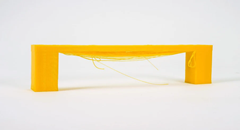
Depending on the settings used, the solidification of the layer may occur too slowly, thus causing it to sagging or lowering, as seen in the following photo.

FDM printer bridging printing tutorial

By the way, below are some tips on how to improve bridging printing.
For tests you can download this sample, which can be printed several times depending on the settings chosen, until you find a satisfactory result:
https://www.thingiverse.com/thing:476845

First you need to make sure that the print stream has been calibrated correctly; in this regard, it is possible to consult the previous lesson, relating to the "Printing Flow Calibration".

At this point, proceeding with the printing of the sample, if the bridging has unsatisfactory quality, it is possible to decrease the printing speed; progressively reducing the speed by about 5 mm/s it is possible to carry out various tests, until the ideal value is found.

FDM printer bridging printing tutorial

Printing temperature also plays a key role in bridging; in fact, the hotter the layer, the longer it takes for its solidification, thus causing a sagging. For this reason, by progressively reducing the printing temperature by about 5 ° C it is possible to carry out various tests, until the ideal value is found.

FDM printer bridging printing tutorial

If the bridge is very long and the geometry of the object allows it, it is often possible to rotate the object until the suspended part disappears completely, as shown in the figure. However, in most cases this is not possible (including the case of printing the sample), so it is a solution that can be counted on very rarely.

FDM printer bridging printing tutorial

Longer Dual Blower Kit

As mentioned from the beginning, for bridging the quality of air emitted by the cooling fan is fundamental, which must be able to instantly solidify the layer; for this reason, if changing the slicing settings is not enough, then the new Longer Dual Blower can help.

Dual blower kit LONGER 3D

The new Longer Dual Blower has been specially designed to allow a faster and more uniform emission of cooling air, thanks to two bilateral turbo fans and a double ventilation duct; in this way the prints are much more detailed and the bridging printing greatly improved.

The installation is very simple, and can be done by consulting this video guide: https://youtu.be/zEA-eM5sfho

Original post: https://eu.longer.net/blogs/academy/fdm-printer-bridging-printing-tutorial

https://eu.longer.net/products/lk5-pro-fdm-3d-printer

By Software | November 27, 2021
LONGER New Dual Blower Kit installation tutorial - LONGER
LONGER New Dual Blower Kit installation tutorial

In FDM 3D printing, cooling performance directly affects print quality. Insufficient cooling can lead to issues such as stringing, sagging edges, and blurred details.

To address these common problems, LONGER 3D has introduced an upgraded accessory — the dual blower kit — designed to significantly enhance printing performance and deliver smoother, more detailed models.

What is a Dual Blower Kit?

The Dual Blower Kit is an enhanced cooling system specifically designed for FDM 3D printers. With a dual-fan structure, it provides more efficient and uniform cooling around the nozzle area.

Compared to traditional single-fan setups, it offers:

  • Stronger airflow output

  • More even cooling across the model

  • Improved printing stability

  • Better performance on complex geometries

Why Upgrade to Dual Cooling Fans?

If you are experiencing any of the following issues, this upgrade can make a noticeable difference:

  • Blurry edges and poor detail definition

  • Rough surfaces or visible layer lines

  • Severe stringing

  • Poor overhang performance

After upgrading, you can expect:

  • Sharper details

  • Smoother surface finish

  • Improved bridging and overhang results

  • More consistent and reliable prints

Compatibility

This Dual Blower Kit is compatible with the following models:

  • LONGER LK4

  • LK4 PRO

  • LK1

  • LK5 PRO

  • U20

  • U30

  • U30 PRO

Installation Video Tutorial

If this is your first time installing an upgrade, we recommend watching the official tutorial video and following along step by step:

👉 https://www.youtube.com/embed/zEA-eM5sfho

Installation Steps

The installation process is straightforward and typically takes about 10–20 minutes:

1️⃣ Remove the original components

  • Remove the hotend fan cover

  • Detach the original sheet metal

2️⃣ Install the dual blower kit

  • Align the new kit with the gantry beam

  • Secure it firmly with screws

3️⃣ Connect the wiring

  • Connect the fan wires according to the instructions

  • Ensure all connections are secure

4️⃣ Test and verify

  • Power on and check fan operation

  • Start printing after confirming everything works properly

Important Notes (Must Read)

⚠️ The wiring method is different from the stock fan

⚠️ You must connect the wires in reverse:

Original red/black → New blue/yellow
Original blue/yellow → Connected in reverse

Incorrect wiring may cause the fan to malfunction or damage the device. Please double-check carefully.

BL Touch Compatibility

If you plan to install a BL Touch auto bed leveling sensor at the same time:

  • Please download the compatible mounting bracket in advance

  • Ensure there is no interference with the dual fan structure

This will help maintain printing accuracy and system stability.

Who Should Upgrade?

This Dual Blower Kit is ideal for:

  • Users looking to improve print quality

  • Makers printing detailed or complex models

  • Users working with PLA / PETG or materials sensitive to cooling

  • Hobbyists and studios aiming for higher print success rates

Final Thoughts

A small upgrade can make a big difference in your FDM 3D printing experience. The LONGER Dual Blower Kit not only significantly improves 3D print quality, providing smoother surfaces, sharper details, and better overhang performance, but also helps you unlock the full potential of your LONGER 3D printer. Whether you are printing PLA, PETG, or other materials that require precise cooling, this upgrade ensures more reliable, consistent results. If you're looking to enhance your FDM 3D printer performance and achieve professional-grade prints, the Dual Blower Kit is a smart and worthwhile investment.

By Software | November 8, 2021