
Longer Ray5 Laser Engraving, Carving and Cutting Applications - LONGER
Longer Ray5 Laser Engraving, Carving and Cutting Applications

A laser engraving machine like Longer Ray5 allows you to realize many types of processing, offering not only high precision but also high-quality details for every type of DIY project. Depending on the type of material, different possibilities of laser processing may occur, including engraving, carving, and cutting. Some materials allow only some of these processes; however, some materials, such as wood, allow you to carry out all three types of processing.

If you are curious to see with your own eyes what types of processing you can achieve with your new Longer Ray5, continue reading this article, and you can find a vast archive of real photographs from the projects made by our customers with Longer Ray5.

Laser Engraving Applications

This type of processing allows you to customize everyday objects in the way you want, for example, by making a greeting card, engraving the name of your pet on its metal plate, or engraving a photograph or an image on ceramic or stone. This process is the easiest to carry out, and if you intend to engrave a difficult material such as metal or ceramics, then it is possible to temporarily color the surface in black so that the laser can engrave the material more easily and then wash off the paint at the end of the realization.

Laser Carving Applications

This type of processing causes a lowering of the surface of the material (usually wood) in a range between a few tenths of a millimeter and a few millimeters, causing a carving. This allows you to have not only a visual representation of the processing, but also feedback to the touch of the surface. Probably this is the most difficult type of processing to achieve, as it is necessary to find the right combination between the various settings of Lasergrbl / Lightburn to carve into the material without burning or cutting it.

Laser Cutting Applications

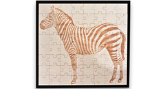
This type of processing allows you to create three-dimensional objects and to give vent to your creativity. In fact, adapting the settings of Lasergrbl / Lightburn to each type of material (usually wood, paper, cardboard, leather, acrylic) it is easy to create a nameplate, a greeting card, a puzzle to compose and even real 3D models. Yes, just engrave and cut the various pieces of a model always using plywood of the same thickness, and then proceed manually to the interlocking of the various pieces to obtain a 3D realization.

Access to unlimited support for image files

Longer Ray5 can engrave many materials and can realize a lot of great projects, all depends from your creativity! And if you need to find new ideas, you can always count on an immense archive of images on the web. Here is a list of resources from which you can take inspiration for your 2D and 3D creations:

https://eu.longer.net/collections/laser-engraver

By Software | July 25, 2022
Longer Ray5 An Introduction to the Laser Engraving Technique - LONGER
Longer Ray5 An Introduction to the Laser Engraving Technique

In physics, the propagation in space of electromagnetic field energy is called electromagnetic radiation. In particular, electromagnetic radiation with a wavelength between about 400 and 800 nm is called visible radiation and is perceptible by the human eye and transformed by the brain into visual sensations; this radiation is what is commonly called light.

In an electromagnetic wave the energy is distributed in discrete and indivisible packets, called quanta, and the quantum of energy of the visible radiation is called a photon. Photons, having energy in the form of an impulse, when they hit matter are able to excite atoms and molecules, which emit quanta at various frequencies that are also detected as heat: this is the physical mechanism at the base of life, why sunlight also produces heat, and how this heat is more or less intense depending on direct or indirect exposure to sunlight.

Although this does not exist in nature, human progress has made possible the ability to "line up" the photons of a light source, concentrating them in a light beam called a laser beam. If the propagation of a light source takes place in the form of a laser, then all the energy is concentrated within a beam of a very small section; therefore, when the laser hits matter, it is instantly able to radiate great power into a very small area, causing a sudden and rapid increase in temperature that alters the state of matter.

Laser engraving

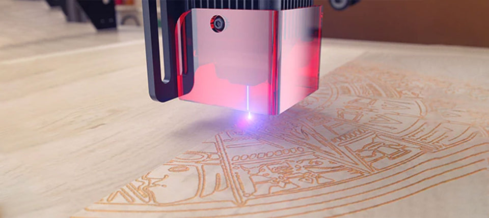
A laser engraving machine is based on a laser module of a given power, capable of generating a laser beam that can be modulated in power within a range between 0% and 100%. When the laser beam hits a surface, it undergoes a rapid increase in temperature that instantly transforms the state of matter by combustion, and the contrast between the lasered surface and the surrounding surface creates the visual effect commonly called laser engraving.

To create an engraving, the laser module is moved in a Cartesian plane X/Y, thus being able to emit a certain power in a given spatial position, and the set of points hit by the laser beam constitute the engraving. Depending on the power with which the laser beam hits each point of the surface, it is more or less able to transform part of the matter, which results in a more or less deep incision with respect to the surface. In fact, when the laser hits a surface, not only is blackening caused by combustion but also a lowering of the surface; the higher the power of the laser, the greater the amount of matter removed. This contrast of hue and depth creates the typical effect of laser engraving, thus being able to make drawings, markings, and engravings on various types of materials.

Difference between laser engraving, carving and cutting

Depending on the type of material, different possibilities of laser processing may occur, including engraving, carving, and cutting. Some materials allow only some of these processes; however, some materials, such as wood, allow you to carry out all three types of processing.

Taking wood as an example, suppose you apply a laser beam on its surface; depending on the power of the beam, the following possibilities occur:

  • The laser has a power capable of burning only the outermost layer of the surface, causing a surface blackening. This process is called laser engraving.

  • The laser has a power capable of transforming the innermost layers of the material, causing a removal of matter and a lowering of the surface in a range between a few tenths of a millimeter and a few millimeters. This process is called laser carving.

  • The laser has a power capable of transforming the innermost layers of the material, causing a removal of matter such that it is greater than the thickness of the material; in this way a hole is created through which light can pass, and this can also lead to the division into several parts of the original surface. Note that this can often be achieved by passing the laser beam at the same point several times so as to remove the entire thickness of the material by the sum of smaller thicknesses removed at each step. This process is called laser cutting.

Note that, even with the same material, these three processing techniques can take different settings, as they depend on the maximum power of the laser beam, the power applied to the processing, the permanence of the laser beam at each surface point (ie the processing speed), the hardness of the type of wood treated, and other factors. Therefore, it is always necessary to carry out empirical tests in order to obtain the correct processing parameters for each type of material, even if of the same type.

The processing parameters, such as power, speed, number of steps, and more, are assigned to the machine using management software such as LaserGRBL. This software takes care of processing in machine code the instructions useful for realizing by laser processing the image or the incisive effect desired by the user. In this way, the machine is able to know point by point where to apply the laser beam, with what power to apply the laser beam, and with what speed to move to a next point, thus being able to transform into reality any type of idea.

https://eu.longer.net/collections/laser-engraver

By Software | July 8, 2022
Longer Ray5 Laser Engraver – Technical Backgroud - LONGER
Longer Ray5 Laser Engraver – Technical Backgroud

Longer Ray5 is an innovative, technological laser engraver able to offer professional performance. In fact, it is equipped with wifi technology with which it is possible to transfer work without the need for cables, the latest security systems and a 5w or 10w laser module able to offer greater performance than those offered by other laser modules of the same nominal power. Let's see together what makes Longer Ray5 one of the best products on the market.

Mainboard MKS DLC32

Longer Ray5 adopts a DLC32 mainboard, characterized by wireless technology, microSD card reading and touchscreen display with graphical interface.

  • The 32bit CPU allows you to process the workload at 240mHz quickly and without delays, thus avoiding lag during laser engraving that could compromise the quality of the final result, as is the case with some 8bit mainboards. Also, it allows to reach a max speed 10.000 mm/min, great results in a short time.
  • The microSD card allows you to transfer from the PC to the Ray5 the work to be carried out at the laser, thus ensuring the possibility of working at any time, even without the availability of a PC. In fact, once you have created the work file on Lasergrbl/Lightburn, just select to export the ".gcode/.nc" to the microSD card, remove the microSD card from the computer and insert it into Ray5. At this point you can start, stop, repeat and edit engraving jobs directly from the Ray5 screen, just as you would with your 3D printer, without needing a PC anymore. In addition, on the microSD card you can keep dozens of work files, so you can repeat them at any time you need them.

  • The touchscreen display is equipped with an intuitive graphic interface, through which you can consult the list of working files on microSD, choose and start an incision, move the axes and fix the "homing" position, turn on and off the laser beam and establish the wireless connection between Ray5 and your wifi internet connection.

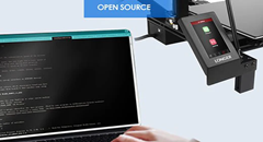
  • The wireless technology of the Ray5 DLC32 mainboard offers unique features, thanks to which it is possible to fully control every aspect of Ray5, remotely and without the need for cables. Simply establish the wireless connection between Ray5 and your wifi internet connection using the touchscreen display interface, after which make a note of the assigned IP address; at this point, by typing in the browser of your PC the IP address marked above, a web page will be opened from which you can fully control Ray5, having a "remote display" of command directly on your PC. In addition, transferring engraving jobs to microSD also becomes easier, as you can transfer files to the microSD via wifi, without the need to physically remove the microSD from Ray5.

  • The mobile APP"MKSLaser" available for Android & iOS allows you to use Ray5 directly from your smartphone, not only to control the machine but also to edit the images andthe related engraving parameters on the move.

Security Protections

Longer Ray5 adopts the latest and most advanced safety protections, so as to guarantee safe use at all times.

  • Thermal protection stops the engraving work in the event that the engraved material should catch fire, alerting the user by means of an audible alarm.
  • Motion protection stops engraving work in case Ray5 is suddenly bumped, preventing damage to the machine.
  • Motionless protection stops engraving work if the laser module remains fixed in the same position for more than 5 seconds; this prevents the fixed laser beam in the same position from igniting the worktop.
  • The eye protection at the base of the laser is made of acrylic material capable of filtering 99% of the laser beam in case it is reflected.
  • Emergency General Protection can be manually activated by the user at any time should any sudden problem occur; just press the ON/OFF button on Ray5 and the machine will shut down immediately.

Updated 10w Laser Module with 0.06x0.06mm spot laser

The new version of Longer Ray5 adopts an improved 10w laser module, which offers much greater performance than competing lasers of the same power; in fact, our laser uses a new technology that allows you to reduce the amplitude of the laser beam, concentrating the laser spot in just 0.06x0.06mm (the spot laser adopted by competitors is usually 0.15x0.15mm), and by concentrating the engraving power within a smaller surface it is possible to obtain results similar to those achievable with competing lasers of greater power or with air-assist. In addition, a focal length of 50mm has been specially chosen, which is optimized for cutting. Thanks to these two technical characteristics, for example, you can cut fir wood 1.4cm thick with only 2 passages (against the 4-5 passages required by competing laser modules of the same power), or 5mm thick plywood with only 1 passage.

  • We performed some demonstration tests, in order to let you see with your own eyes our tests the great performances provided by our 10w - 0.06x0.06mm - laser module. Give a look at this following table, you will be amazed!

Model

Material

Action

Thickness

Power

Speed

Cycles

Remarks

LONGER RAY5 10W

Basswood

Engrave

-

35%

3000 mm/min

1

LONGER RAY5 10W

Hardwood

Engrave

-

40%

2000 mm/min

1

LONGER RAY5 10W

Bamboo

Engrave

-

35%

3000 mm/min

1

LONGER RAY5 10W

Acrylic

Engrave

-

35%

3000 mm/min

1

LONGER RAY5 10W

KraftPaper

Engrave

-

20%

3000 mm/min

1

LONGER RAY5 10W

Mirror

Engrave

-

35%

2500 mm/min

1

LONGER RAY5 10W

Leather

Engrave

-

20%

3000 mm/min

1

Light color. It needs to be adjusted based on different colors.

LONGER RAY5 10W

Denim

Engrave

-

25%

2000 mm/min

1

LONGER RAY5 10W

Powder Coated Metal

Engrave

-

LONGER RAY5 10W

Anodised Aluminium

Engrave

-

LONGER RAY5 10W

Ceramic

Engrave

-

LONGER RAY5 10W

Glass

Engrave

-

70%

1000 mm/min

1

Color with dark paint before engrave.

LONGER RAY5 10W

Stainless Steel

Engrave

-

100%

400 mm/min

1

LONGER RAY5 10W

Basswood

cut

2 mm

LONGER RAY5 10W

Basswood

cut

3 mm

LONGER RAY5 10W

Basswood

cut

8 mm

100%

120 mm/min

1

LONGER RAY5 10W

Basswood

cut

10 mm

100%

100 mm/min

2

LONGER RAY5 10W

Pinewood

cut

14 mm

100%

100 mm/min

2

LONGER RAY5 10W

Acrylic

Cut

3 mm

100%

180 mm/min

1

LONGER RAY5 10W

KraftPaper

Cut

0.1 mm

100%

5000 mm/min

1

LONGER RAY5 10W

Leather

Cut

Light color. It needs to be adjusted based on different colors.

LONGER RAY5 10W

Denim

Cut

  • To compare the differences between Longer 10w - 06x0.06mm - lasermodule and our Longer 5w - 0.08x0.08mm - laser module, you can check this table.

Model

Material

Action

Thickness

Power

Speed

Cycles

Remarks

LONGER RAY5 5W

Basswood

Engrave

-

100%

2000 mm/min

1

LONGER RAY5 5W

Plywood

Engrave

-

100%

2000 mm/min

1

LONGER RAY5 5W

Pine

Engrave

-

100%

2000 mm/min

1

LONGER RAY5 5W

Stainless Steel

Engrave

-

100%

200 mm/min

1

Color with dark paint before engrave.

LONGER RAY5 5W

Anodised Aluminium

Engrave

-

100%

3000 mm/min

1

Dark color. It needs to be adjusted based on different colors.

LONGER RAY5 5W

Cotton Cloth

Engrave

-

100%

1000 mm/min

1

White color. It needs to be adjusted based on different colors.

LONGER RAY5 5W

Leather

Engrave

-

100%

3000 mm/min

1

White color. It needs to be adjusted based on different colors.

LONGER RAY5 5W

Powder Coated Metal

Engrave

-

100%

500 mm/min

1

Dark color. It needs to be adjusted based different colors.

LONGER RAY5 5W

Solid Wood

Engrave

-

80%

3000 mm/min

1

It needs to be adjusted based on different woods.

LONGER RAY5 5W

Glass

Engrave

-

100%

700 mm/min

1

Color with dark paint before engrave.

LONGER RAY5 5W

Basswood

Cut

2 mm

100%

300 mm/min

1

LONGER RAY5 5W

Plywood

Cut

4 mm

100%

100 mm/min

1

LONGER RAY5 5W

Pine

Cut

6 mm

100%

120 mm/min

2

LONGER RAY5 5W

Acrylic

Cut

2 mm

100%

120 mm/min

2

LONGER RAY5 5W

Paperboard

Cut

2mm

100%

1000 mm/min

2

LONGER RAY5 5W

Kraft Paper

Cut

0.15mm

80%

3000 mm/min

1

LONGER RAY5 5W

KT Board

Cut

5mm

100%

300 mm/min

2

White color. It needs to be adjusted based on different colors.

LONGER RAY5 5W

Non-woven Fabrics

Cut

0.5mm

100%

800 mm/min

1

White color. It needs to be adjusted based on different colors.

LONGER RAY5 5W

Cotton Cloth

Cut

1mm

100%

400 mm/min

1

White color. It needs to be adjusted based on different colors.

LONGER RAY5 5W

Leather

Cut

0.7mm

100%

500 mm/min

1

White color. It needs to be adjusted based on different colors.

Compatible with a wide variety of materials and unlimited support for image files

Longer Ray5 can engrave many materials, including wood, aluminum, ceramics, glass, and much more, it all depends on your creativity! And if you need to find new ideas, you can always count on an immense archive of images on the web. Here is a list of resources from which you can take inspiration for your 2D and 3D creations:

https://eu.longer.net/collections/laser-engraver

By Software | July 8, 2022
Longer LK4 Pro & LK5 Pro – Upgrades by @Ciubecca - LONGER
Longer LK4 Pro & LK5 Pro – Upgrades by @Ciubecca

All Longer 3D printers offer excellent performance and guarantee high print quality, however some users love to install upgrades useful to change the aesthetic appearance or characteristics of the printer. For this reason,。

this article intends to present some of the most installed upgrades by users, offered by @Ciubecca Nicola.

1、LONGER LK4Pro & LK5Pro Display Cover


This upgrade allows you to install a cover on the display of the Longer LK4PRO & LK5PRO printers, so as to protect the screen from dust when the printer is not in use

Download link: https://www.thingiverse.com/thing:4929422

2、LONGER LK4Pro & LK5Pro Adjustable LED Light Bar Mount


This upgrade allows you to install a lamp through an adjustable stand, so as to obtain a good illumination of the printing plate of LK4PRO & LK5PRO.

Download link: https://www.thingiverse.com/thing:4980580

3、LONGER LK4Pro & LK5Pro Mini SD Card/USB Holder


This upgrade allows you to install a holder for microSD cards, USB pendrives and SD cards, so you always have any type of flash memory next to the printer

Download link: https://www.thingiverse.com/thing:5230892

4、LONGER LK4Pro & LK5Pro Front rail cover with Bed Leveling Reminder


If you do not need the previous Card Holder, then this upgrade can be a good choice; this upgrade is a reminder that allows you to remember from which direction you have to turn the leveling knobs to raise or lower the printing surface

Download link: https://www.thingiverse.com/thing:4981797

5、LONGER LK4Pro & LK5Pro Screw Cap


An upgrade as simple as it is functional, of the simple caps to cover the screws of the aluminum frame of the LK4PRO & LK5PRO printers. Choose your favorite color to customize your printer to the maximum!

Download link: https://www.thingiverse.com/thing:5186277

6、LONGER LK4Pro & LK5Pro Spool Clamp


Some filament coils tend to move on the Spool Holder; therefore, if this is a problem for you then you can install this upgrade, which allows you to hold the coil in its position

Download link: https://www.thingiverse.com/thing:5186749

7、LONGER LK4Pro & LK5Pro Flexible Arms


This upgrade consists of a flexible arm, which was used to install a camera that can record the printing process. However, if you have a different camera or if you don't need a camera, then you can modify the original design and use the flexible arm for any kind of customization you have in mind. Bring your ideas to life!

Download link: https://www.thingiverse.com/thing:5186245

Final Result

These upgrades offer practical ways to customize your LONGER LK4 PRO and LK5 PRO, improving convenience and enhancing the overall printing experience.

By Software | June 16, 2022
First Layer Calibration - LONGER
First Layer Calibration

The calibration of the first layer takes place by calibrating the distance between the tip of the nozzle and the surface of the printing plate; in this way the extruded plastic will stick correctly to the plane, being crushed slightly and correctly.

Longer 3D printers are equipped with a menu accessible from a display that allows you to calibrate accurately and precisely, by measuring it at 5 predetermined points. For calibration it is enough to leave the space of a sheet of paper between the tip of the nozzle and the surface of the plate, so that the sheet can move freely but with a slight friction, simply by turning each of the 4 knobs to manually adjust the distance between the nozzle and the plane.

Once the calibration has been carried out correctly, it is possible to make a test print to evaluate the quality of the first layer, which will be perfect if the calibration has been carried out correctly or of poor quality if the calibration has been carried out incorrectly. Proper adjustment ensures a uniform and perfect surface, without gaps between the lines, nor ridges.

An extrusion too far from the printing plane is recognized by round lines instead of crushed, far from each other rather than united; an extrusion too close to the printing plane is recognized by lines crushed completely, too close to each other almost to overlap and create ridges that curl upwards.

In case of incorrect calibration, the following problems may occur: if the nozzle is too far from the print surface, there is a risk that the print will not stick properly, causing a harmful accumulation of material around the nozzle, instead if set too close, an occlusion of the nozzle, excessive adhesion to the printing plate or even permanent damages at the printing plane.

Therefore, it is a good idea not only to accurately calibrate the first layer, several times if necessary, and above all to monitor the printer every time you start a new print until the first layer has been completed correctly.

Sometimes, the first layer may fail to adhere to the print plane despite the calibration being done correctly. In these cases, you can proceed with the thorough cleaning of the printing surface, so as to remove the accumulated dirt; in case the problem persists, you can proceed with the increase of the flow related to the first layer, a topic that will be covered in a future lesson.

Once a perfect calibration has been obtained, this will not be eternal: the first layer calibration will have to be checked periodically, and surely it will have to be done again every time you move the printer to a different place, you make the nozzle replacement, the extruder change, the replacement of the plane or any other modification to one of the 3 axes.

In some case, it could be found that the calibration is impossible to carry out on the 5 points, that is, the 4 corners of the plane are well calibrated while the center is too close to the tip of the nozzle. This could be caused by incorrect placement of the Z endstop.

Longer 3D printers have a sticker that indicates where endstop Z should be placed. However, if endstop Z is placed too low, as a result it will be necessary to lower the printing plane as well, screwing more the 4 adjustment knobs; on the other hand, excessively screwing the corners inevitably causes a deformation of the aluminum top, which takes on a curved shape with the highest center of the corners.

In these cases, it is possible to place endstop Z higher, so as to be able to raise even the 4 corners of the plane and cancel the curvature. On the other hand, it is advisable not to exceed the positioning of endstop Z at the top, as this would cause an instability of the printing plane due to insufficient screwing of the 4 levelling knobs.

Above is the introduction of the first layer calibration, hope it can help you. If you still have any questions during the operation, please visit our Support Page. Our knowledgeable staff is happy to assist you and your team with any questions.

After mastering the above information, why not take a look at our exceptionally outstanding laser engraving machine, the Longer Laser B1 40W ?Unlock the pinnacle of laser engraving and cutting prowess with the B1 40W. Where precision meets versatility and innovation, seize the power to transform your visions into tangible achievements. With its powerful engraving and cutting capabilities, it transcends boundaries to become the best engraving machine and best laser cutter for a variety of materials. From wood, metal, acrylic, glass to leather and more, there are no limits to your creativity.

By Software | June 16, 2022
Printing Flow Calibration - LONGER
Printing Flow Calibration

In 3D printing, extrusion flow is a key aspect to consider if you want to obtain not only quality prints, but also dimensionally correct prints.

The flow is closely related to the speed of rotation of the gear wheel attached to the extrusion motor; the faster it rotates in a certain time interval, the more filament will be extruded during that interval. For this reason it is necessary to set the correct amount of flow, corresponding to the exact amount of molten material needed to correctly compose the printed object.

Depending on the amount of flow per unit of time, 3 scenarios can occur:

  • Underextrusion(too low flow), which occurs when little material is extruded and has prints with small gaps that appear between two layers or between two perimeter lines
  • Extrusion(correct flow), which when the right amount of material is extruded and has prints free of external defects
  • Overextrusion(too high flow), which occurs when too much material is extruded and features blobs prints on the outer walls and accumulation of unnecessary material on the upper layers

If the prints are affected by underextrusion, then it will be necessary to increase the print flow; instead, in case of overextrusion it will be necessary to decrease the print flow. In order to determine the exact amount of decrease/increase in flow, empirical tests can be failed to provide accurate reference data.

Starting from the premise that a underextrusion produces prints smaller than expected while an overextrusion produces prints larger than expected, in order to empirically verify the amount of flow we proceed as follows:

  • Download the following calibration cube.stl:

https://thingiverse.com/thing:5118535

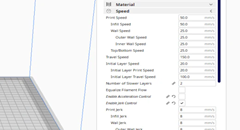
  • Import the cube.stl into Cura and apply the following slicing settings:

  • Print the cube, which will have only one perimeter wall, empty and without a top layer

  • When printing is complete, proceed to the measurement of the walls with a gauge

Each wall will have a certain size, which may be less, equal or greater than 0.4mm; from the average of these values, the flow is calculated by applying the following formula:

Therefore, assuming that the average of the measured walls is 0.5mm wide despite it should be 0.4mm, the flow to be set turns out to be:

The result obtained must be set in the following Cura menu:

However, you have to pay close attention to the flow set, because even if it is the result of mathematical calculations, it is not always absolutely correct. In fact, the calculated flow can be to include errors due to a bad measurement with the caliber, from a bad leveling of the printing plane, and so on; therefore, it is a good idea to repeat the printing of the test cube several times to check for any variations, and above all it is necessary to verify that the prints do not yet have defects despite the new flow has been set correctly.

This means that, if, for example, mathematical calculations have returned a value of 80% as the correct flow, perhaps the best value for prints is that of an 85% stream. Then once the new flow is set, we proceed by increasing/decreasing the new value based on any aesthetic defects of the prints.

We proceed by applying a visual method:

  • Restore Cura to default settings
  • Print the cube.stl normally, with infill
  • Visually examine the print quality of the cube

  • If the flow has been set correctly, the upper layers will be smooth, shiny and without scarring or filament accumulations near the perimeters, with the layers perfectly joined.
  • If there is too much material near the perimeters, slightly decrease the flow value and rerun the test.

If there are visible gaps between the layer lines, slightly increase the flow value and run the test again.

https://eu.longer.net/collections/3d-printers-1

By Software | June 16, 2022
Bridging Printing
Bridging Printing

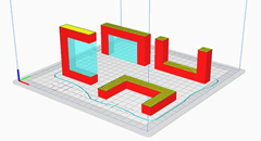
The FDM 3D printing consists of a series of layers of molten material placed on top of each other; in this way, complex objects are created through a succession of layers. However, often some layers must be placed in areas without a base, so the layer is printed literally in a vacuum and it will inevitably fall down, but to overcome this problem it is possible to use supports, which act as a temporary scaffolding and can be removed once the print has been completed.

In some special cases it is possible to print suspended layers, without the use of supports. It may seem like an impossible feat, but over short straight distances you can print in a vacuum by instantly solidifying the layer using the air from the printer fans, thus creating a solid connection. This phenomenon is called Bridging and can be accomplished by means of some key print settings, such as flow, print speed and cooling.

Depending on the settings used, the solidification of the layer may occur too slowly, thus causing it to sagging or lowering, as seen in the following photo.

By the way, below are some tips on how to improve bridging printing.
For tests you can download this sample, which can be printed several times depending on the settings chosen, until you find a satisfactory result:
https://www.thingiverse.com/thing:476845

First you need to make sure that the print stream has been calibrated correctly; in this regard, it is possible to consult the previous lesson, relating to the "Printing Flow Calibration".

At this point, proceeding with the printing of the sample, if the bridging has unsatisfactory quality, it is possible to decrease the printing speed; progressively reducing the speed by about 5 mm/s it is possible to carry out various tests, until the ideal value is found.

Printing temperature also plays a key role in bridging; in fact, the hotter the layer, the longer it takes for its solidification, thus causing a sagging. For this reason, by progressively reducing the printing temperature by about 5 ° C it is possible to carry out various tests, until the ideal value is found.

If the bridge is very long and the geometry of the object allows it, it is often possible to rotate the object until the suspended part disappears completely, as shown in the figure. However, in most cases this is not possible (including the case of printing the sample), so it is a solution that can be counted on very rarely.

Longer Dual Blower Kit

As mentioned from the beginning, for bridging the quality of air emitted by the cooling fan is fundamental, which must be able to instantly solidify the layer; for this reason, if changing the slicing settings is not enough, then the new Longer Dual Blower can help.

The new Longer Dual Blower has been specially designed to allow a faster and more uniform emission of cooling air, thanks to two bilateral turbo fans and a double ventilation duct; in this way the prints are much more detailed and the bridging printing greatly improved.

The installation is very simple, and can be done by consulting this video guide: https://youtu.be/zEA-eM5sfho

The purchase is available on the Official Longer Store:
https://eu.longer.net/collections/accessories/products/longer-new-dual-blower-fan-kit

https://eu.longer.net/products/lk5-pro-fdm-3d-printer

By Software | June 16, 2022
Printing Supports - LONGER
Printing Supports

FDM 3D printing consists of a series of layers of molten material placed on top of each other; in this way, complex objects are created through a succession of layers. However, often some layers must be placed in areas without a base, so the layer is printed literally in a vacuum and it will inevitably fall down, but to overcome this problem it is possible to use supports, which act as a temporary scaffolding and can be removed once the print has been completed.

In a previous lesson, we saw how in some special cases it is possible to print suspended layers, without the use of supports, using the phenomenon called Bridging, but this technique is limited to particular designs mostly straight and of short distances. For most prints there will inevitably be a need to use Printing Supports.

As anticipated, the supports are printed structures that are not part of the original design, but are scaffolding external to the design that are used temporarily for printing the object, and in particular serve to ensure that the cantilevered parts of the object are extruded over a solid structure instead of in a vacuum, so as not to collapse downwards. These support structures are temporary because at the end of printing, they will have to be removed, thus having a model printed according to the original design.

In the Cura slicer there are various types of supports to choose from, and most of them are equivalent, that is, choosing one type instead of another does not make a big difference; they are mainly based on vertical structures, more or less dense, and a good default configuration of the supports can be indicated in the following photo:

A separate case is the Tree Supports, which tend to be less dense and easier to remove at the end of printing, since just like a tree these supports have a common base at the bottom and expand upwards in more branches just with a tree. Therefore, a smaller support surface at the bottom corresponds to a greater support surface at the top, and this saves material for the realization of the supports and facilitates the removal of the supports thanks to their particular upward development configuration.

The example below shows how, with the same model, the two different types of support take on a different development, while performing the same function:

Although tree supports always seem to be the best choice for various reasons, in reality it is necessary to evaluate on a case-by-case basis what type of support to use, as depending on the geometry of the model it may be more convenient to use classic vertical supports, so as to guarantee greater resistance during printing. In any case, the best way to get answers in this regard is to empirically test the various types of support and evaluate those that best suit the type of model to be printed.

https://eu.longer.net/products/lk5-pro-fdm-3d-printer

By Software | June 16, 2022
Nozzle Size Comparing - LONGER
3D Printer Nozzle Size Comparing: Speed, Detail & Layer Height Explained

In 3D printing, the nozzle diameter plays a key role in determining the maximum layer height you can use. As a general rule, the maximum layer height is about 80% of the nozzle’s diameter. For example:

  • With a 0.4 mm nozzle, the layer height can go up to 0.32 mm.

  • With a 0.8 mm nozzle, it can reach 0.64 mm.

  • With a 0.2 mm nozzle, the maximum is 0.16 mm.

What’s important to note is that the nozzle size only limits the maximum layer height — not the minimum. This means that even with a large 0.8 mm nozzle, you can still print with fine resolutions like 0.05 mm, just as you would with smaller nozzles.

In simple terms, larger nozzles allow faster printing while still being capable of high detail, and smaller nozzles focus on fine detail but print more slowly.

By Software | June 16, 2022
Tolerance Test for Joints - LONGER
Tolerance Test for Joints

When creating laser-cut assemblies, one of the most common challenges is achieving the correct fit between connected parts. A tolerance test for joints helps determine whether pieces fit too tightly, too loosely, or exactly as intended. Running this test before producing a full project can reduce wasted materials and improve assembly quality.

Table of Contents

  • What This Guide Covers
  • Why This Process Matters
  • Before You Start
  • Requirements
  • Precautions
  • Step-by-Step Tutorial
  • Common Problems and Solutions
  • Tips for Better Results
  • Frequently Asked Questions
  • Final Thoughts

What This Guide Covers

This guide explains how to perform a tolerance test for joints for laser-cut parts and assemblies. It helps beginners understand why fit calibration matters and how testing affects final project quality.

Quick Answer

A tolerance test for joints is a small calibration process used before manufacturing final parts. It allows users to determine the ideal fit between connected laser-cut pieces by evaluating how tightly or loosely components assemble together.

Running a test before a full production job helps reduce material waste and improves dimensional accuracy.


Why This Process Matters

Even when using the same machine repeatedly, several factors can affect the fit of laser-cut joints:

  • Material thickness may vary
  • Different materials cut differently
  • Laser kerf can change
  • Machine calibration affects results
  • Power and speed settings may influence cut width

A design that fits perfectly in one material may become too tight or too loose in another.

Testing first helps you:

  • Improve assembly accuracy
  • Reduce wasted materials
  • Avoid repeated cutting attempts
  • Create consistent press-fit results
  • Increase project reliability

For projects involving:

  • Boxes
  • Mechanical assemblies
  • Snap-fit structures
  • Press-fit designs
  • Interlocking components

Tolerance testing becomes especially important.


Before You Start

Before beginning the tolerance test process, ensure your machine is operating correctly.

Check the following:

  • Machine is powered correctly
  • Laser focus is properly adjusted
  • Material is flat
  • Lens is clean
  • Working surface is stable

If additional setup information is required:

Follow official machine specifications or instructions.


Requirements

You may need:

  • Laser engraver or cutter
  • Test material
  • Joint test file
  • Computer with design software if required
  • Measuring tools if needed

Use the same material type and thickness planned for the final project whenever possible.


Precautions

Before running the test:

  • Verify that material thickness matches your intended project material
  • Ensure the material is secured
  • Keep the laser area ventilated
  • Do not leave the machine unattended during operation
  • Follow machine safety guidelines

Avoid making assumptions about material dimensions.

Material manufacturers often list nominal thickness values, but actual thickness can vary.


Step-by-Step Tutorial

Because the original procedure and exact operating sequence are the source of truth, preserve all original steps exactly as provided in the official tutorial.

If specific values, menus, file names, measurements, or settings are required:

Follow official machine specifications or instructions.

Step 1: Prepare the Joint Test File

Action

Prepare the official joint tolerance test file from the original tutorial.

Why this matters

The test file is designed to compare multiple fit variations in a controlled way.

Expected result

The file is ready for processing.

Important notes

Do not modify:

  • Dimensions
  • Slot values
  • Labels
  • File names

Step 2: Import the Test File

Action

Load the official test file into your software.

Why this matters

Correct file loading ensures the intended geometry remains unchanged.

Expected result

The design appears correctly in the workspace.

Important notes

Avoid rescaling the model.

Even small changes may affect the test outcome.


Step 3: Configure Machine Settings

Action

Apply the settings specified in the original tutorial.

Why this matters

Laser parameters influence cut width and therefore joint fit.

Expected result

Machine settings match official recommendations.

Important notes

Do not change:

  • Power values
  • Speed values
  • Pass numbers
  • Material settings

Use only official values.


Step 4: Start the Test

Action

Run the joint tolerance test process.

Why this matters

This step creates physical samples that allow fit evaluation.

Expected result

The machine cuts the test pieces successfully.

Important notes

Observe the process for:

  • Excessive burning
  • Incomplete cutting
  • Unexpected movement

Step 5: Evaluate the Results

Action

Assemble and compare the test joints.

Why this matters

The purpose is identifying the best fit for your material.

Expected result

You can determine whether joints are:

  • Too tight
  • Too loose
  • Properly fitted

Important notes

The ideal fit should:

  • Hold firmly
  • Avoid excessive force
  • Allow consistent assembly

Common Problems and Solutions

Problem Possible Cause Solution
Joint too tight Material thicker than expected Use the tested fit result from the calibration sample
Joint too loose Material thinner than expected Recheck material dimensions
Parts do not separate cleanly Incomplete cutting Follow official machine specifications or instructions
Burn marks on edges Cutting conditions may require adjustment Follow official machine specifications or instructions
Fit differs between materials Material properties vary Run a new tolerance test for each material type
Results vary between runs Machine calibration differences Verify machine condition and setup

Tips for Better Results

Use actual project materials

Different materials behave differently during cutting.

Testing on scrap material from the final project batch often produces better consistency.

Test every material change

Examples include:

  • Different plywood brands
  • Acrylic sheets
  • MDF
  • Basswood

Even identical labeled thicknesses can behave differently.

Keep optics clean

Dust accumulation on lenses can affect cut consistency.

Store successful settings

Record:

  • Material type
  • Thickness
  • Test outcome

Building a material database can save time later.


Frequently Asked Questions

1. Why is my laser-cut joint too tight?

Material thickness variation and laser kerf differences commonly affect fit.

Run a tolerance test before producing the final parts.


2. Do I need to test every material?

Yes. Different materials can produce different cutting behavior even if thickness values appear identical.


3. Can I use the same settings for plywood and acrylic?

Not necessarily.

Different materials react differently during cutting.

Follow official machine specifications or instructions.


4. Why do my assembled parts crack?

Excessively tight joints may create stress during assembly.

Perform fit testing before full production.


5. What is kerf?

Kerf is the material removed during cutting.

The laser beam width creates a small cut gap that influences fit accuracy.


6. Should I modify the official test dimensions?

No.

Keep all original dimensions unchanged.

Changing dimensions may invalidate the results.


7. Why does the fit change on different days?

Environmental conditions and material variation can influence results.

Running a quick calibration test before important projects can improve consistency.


Final Thoughts

A tolerance test for joints is a simple but valuable process for improving laser-cut assembly accuracy. Instead of discovering fit problems after producing a complete project, testing first helps identify the correct joint behavior with minimal material waste.

Maintaining the original workflow and official parameters is important. When details are not provided in the source documentation, always:

Follow official machine specifications or instructions.

By Software | June 16, 2022